AWD EJ2 Build


Thread Starter
Honda-Tech Member
Joined: Nov 2006
Posts: 573
Likes: 0
From: Preston, Lancashire, United Kingdom
Thanks mate..
Actually, not as many as it looks...
I have redesigned a few things.. The ALS, Engine position module, Coil Pack Driver are all in the same slotted enclosure (work in progress). There are only a few separate units;
Thermal Management Unit
Fuel Pump Controller (now much smaller)
Drive by Wire / Power Steering Controller
ALS, EPM, COP driver
Rear Wing Controller
4wd Controller
Dash Controller
and thats it..
Honda-Tech Member

Joined: Apr 2003
Posts: 1,786
Likes: 0
From: San Jose, CA
Nice thread, my Dad and I think you're nuts (in a good way) ") . But we did have a question, and it might just be that we're spoiled living in silicon valley, but why aren't you making your own PCB's or buying custom ones?
. But we did have a question, and it might just be that we're spoiled living in silicon valley, but why aren't you making your own PCB's or buying custom ones?
. But we did have a question, and it might just be that we're spoiled living in silicon valley, but why aren't you making your own PCB's or buying custom ones?
Thread Starter
Honda-Tech Member
Joined: Nov 2006
Posts: 573
Likes: 0
From: Preston, Lancashire, United Kingdom
Thanks mate- and your dad!
I dont have my own PCB equipment yet.. Rather pricey over here lol
I planned to use these as prototype, when i was positive they were correct and debugged i was going to have them custom made.. To be honest i wish i was in the states, everything over here is so expensive..
I dont have my own PCB equipment yet.. Rather pricey over here lol
I planned to use these as prototype, when i was positive they were correct and debugged i was going to have them custom made.. To be honest i wish i was in the states, everything over here is so expensive..

Honda-Tech Member
Joined: Jan 2011
Posts: 20
Likes: 0
 I'll give you a shout once it warms up a touch, otherwise the TC will be working overtime and not really best road conditions to show you it bud. Soon though I'm sure.
OG Hot Rodder
Joined: Sep 2004
Posts: 145
Likes: 1
From: San Jose, CA, USA
My son Michael referred me to this thread. We think you are having way too much fun.
One thing you may want to consider is working with www.4pcb.com. They have a barebones option that doesn't do soldermasks or silk screening, but it is really cheap and fast: http://www.4pcb.com/index.php?load=content&page_id=132
Here is their information for international customers: http://www.4pcb.com/index.php?load=content&page_id=279
You download their PCB Artist application, which is a pretty easy to use CAD tool. Design your schematics and your PCB and then submit your order with a credit card. The barebones price is based on the size of the PCB, and is as cheap as $10 per board for small footprints. Turnaround is very fast.
The component library isn't too big, but it is pretty easy to add your own. And thier email support is very good.
I have been designing aftermarket circuits for the Mustang crowd for a few years now, and have very good luck with these guys. And the circuits are extremely reliable, even with the mistakes I have made. It is pretty easy to cut traces and add blue wires to fix errors in prototypes.
If you haven't yet, you should also add an 18V TVS (Transient Voltage Suppressor) across the power supply and a Shottky diode in series with the battery voltage input for your designs. The diode protects against someone hooking jumper cables backwards and the TVS protects against the battery coming unhooked (or switched off for a track car) while the alternator is spinning. That situation can cause huge voltage spikes on the line.
Something to consider, anyway.
PS, I like MOSFETs and PICs too.
Last edited by MarkOlson; Jan 16, 2012 at 08:04 PM.
Thread Starter
Honda-Tech Member
Joined: Nov 2006
Posts: 573
Likes: 0
From: Preston, Lancashire, United Kingdom
Thanks very much for that info, ill have to check them out... Youre talking $7 for 1 PCB here, and that is barebones! Crackers!
I have a PCB designer tool so it would be great if i could use that, but ill have a look at the site in a minute..
Not to worry, i have already added protection.. I had to use a TVS anyway as turning headlights on was effecting timing on the PIC circuits. Needed something more than the usual noise suppression caps..
At last ive found someone with the same affinity for MOSFETs and PICs! 2 underappreciated components in my opinion.. Despite the ridiculous cost of PICs..
Thread Starter
Honda-Tech Member
Joined: Nov 2006
Posts: 573
Likes: 0
From: Preston, Lancashire, United Kingdom
Sorry chaps i didnt see your posts...
At the moment i really dont have many pictures.. Not until the respray is done..
Basically, the radiator is mounted in front of the fuel cell, and tilted backwards with the two fans on the back.. There are going to be 2 NACA inlet ducts on the rear quaters under the back windows. They feed the radiator with 4 3" ducts hidden behind the rear door panels.
There will be a fibreglass cowl fitted to the radiator which connects to the 3" tubes. There will be a duct on the rear of the radiator which feeds to the number plate recess and additional holes cut in the steelwork behind the bumper.
Awesome, i look forward to seeing it mate!
Well, having cut down the number of units, the ECU, engine position module, cooling controller, drive by wire, FJO injector driver and a fuse box will be mounted on a shock absorbed aluminium panel under the passenger carpet. The fuel pump controller will be mounted on the rear passenger side floor, the active wing controller will be mounted in a cage where the rear passenger legs will be, this cage will provide strong anchor points for the passenger front harness. The AWD computer will be mounted in front of the centre rear passenger, and the dash computer in front of the drivers side rear passenger in a similar frame to the active wing system.
Basically, the radiator is mounted in front of the fuel cell, and tilted backwards with the two fans on the back.. There are going to be 2 NACA inlet ducts on the rear quaters under the back windows. They feed the radiator with 4 3" ducts hidden behind the rear door panels.
There will be a fibreglass cowl fitted to the radiator which connects to the 3" tubes. There will be a duct on the rear of the radiator which feeds to the number plate recess and additional holes cut in the steelwork behind the bumper.
Well I've just heard my 4th gears and other gearbox parts have come in so 2day service from the states it is! I'll give you a shout once it warms up a touch, otherwise the TC will be working overtime and not really best road conditions to show you it bud. Soon though I'm sure.
I'll give you a shout once it warms up a touch, otherwise the TC will be working overtime and not really best road conditions to show you it bud. Soon though I'm sure. Well, having cut down the number of units, the ECU, engine position module, cooling controller, drive by wire, FJO injector driver and a fuse box will be mounted on a shock absorbed aluminium panel under the passenger carpet. The fuel pump controller will be mounted on the rear passenger side floor, the active wing controller will be mounted in a cage where the rear passenger legs will be, this cage will provide strong anchor points for the passenger front harness. The AWD computer will be mounted in front of the centre rear passenger, and the dash computer in front of the drivers side rear passenger in a similar frame to the active wing system.
OG Hot Rodder
Joined: Sep 2004
Posts: 145
Likes: 1
From: San Jose, CA, USA
Thread Starter
Honda-Tech Member
Joined: Nov 2006
Posts: 573
Likes: 0
From: Preston, Lancashire, United Kingdom
The main load is taken through 2 solid u-shaped brackets 1/8" thick. This is bolted to 4 steel telescopic tubes 1/2" diameter by 1/16" thick.
The load is transferred to the boot lid itself, where a large supporting structure triangulates it down to the slam panel and hinges..
Obviously the proof will be in the testing but im quite confident..
Thread Starter
Honda-Tech Member
Joined: Nov 2006
Posts: 573
Likes: 0
From: Preston, Lancashire, United Kingdom
Look what I received tonight, this is a picture of the laser cut / engraved dash control panel fascia.
Hopefully ill have it on Thursday to assemble but needless to say im very happy with how it came out. Ill just need to send across the other 4 panels for work!!
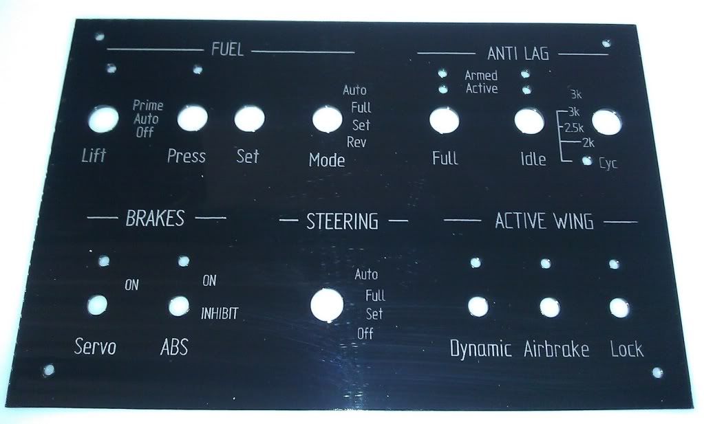
Hopefully ill have it on Thursday to assemble but needless to say im very happy with how it came out. Ill just need to send across the other 4 panels for work!!

Thread Starter
Honda-Tech Member
Joined: Nov 2006
Posts: 573
Likes: 0
From: Preston, Lancashire, United Kingdom
Thanks mate!
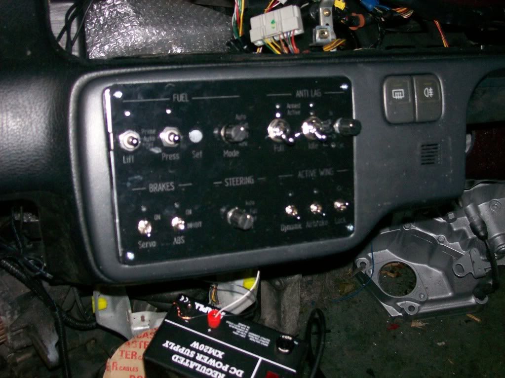
The panel arrived tonight, so i took some time to assemble it.. The LEDs havnt come so i used some i had on the shelf, these are ultra high brightness non-diffused so you can see they are too focused on the rear of the panel. But it gives the idea..
Please forgive the finger prints and its obviously not fully fitted in the dash yet..
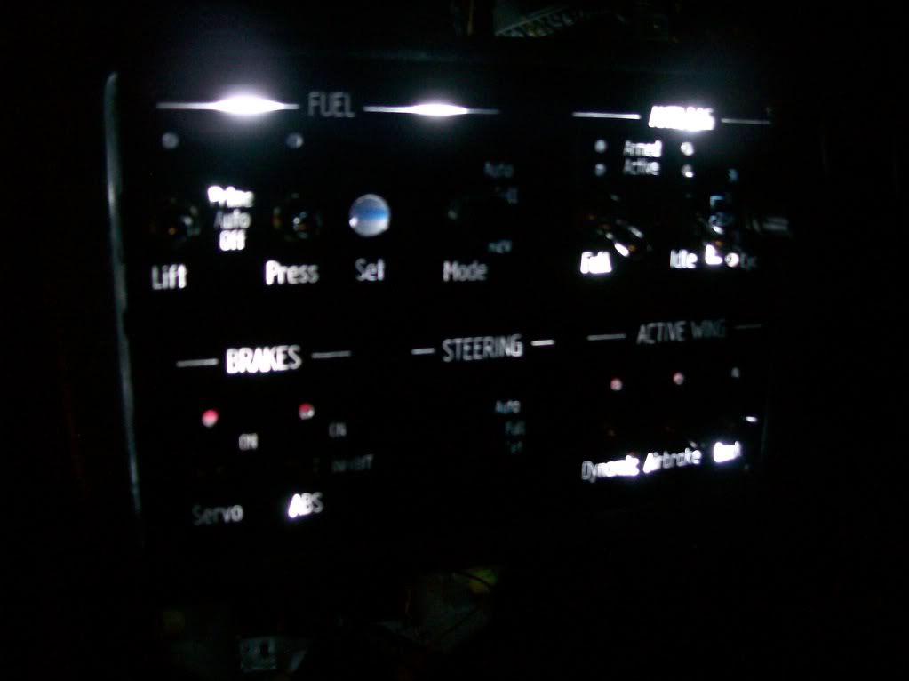
Also excuse the awful camera- it really doesnt handle dark very well
The panel arrived tonight, so i took some time to assemble it.. The LEDs havnt come so i used some i had on the shelf, these are ultra high brightness non-diffused so you can see they are too focused on the rear of the panel. But it gives the idea..
Please forgive the finger prints and its obviously not fully fitted in the dash yet..
Also excuse the awful camera- it really doesnt handle dark very well
Thread Starter
Honda-Tech Member
Joined: Nov 2006
Posts: 573
Likes: 0
From: Preston, Lancashire, United Kingdom
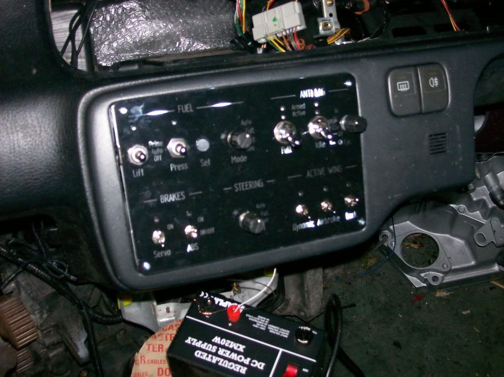
Ive managed to finish the dash panel, also got a small video if the power up sequence (the brightness of the control panels is controlled by the main dash panel's lighting controller).