

AWD EJ2 Build

Thread Starter
Honda-Tech Member
Joined: Nov 2006
Posts: 573
Likes: 0
From: Preston, Lancashire, United Kingdom
Bloody hell, thanks mate- i think thats the best compliment ive ever had!
Ok a bit bored today so i decided to clean the garage... cant do anything on the rear wing until the electronics come...
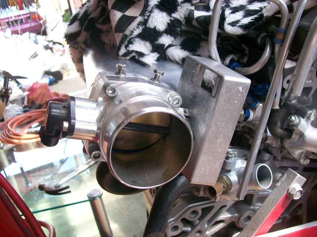
Until then i decided to add another bracket to the top of the engine, its a guide for the EGT probe.. Nothing fancy..
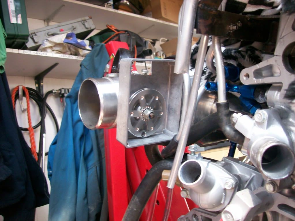
Also started some work on the drive by wire actuator.. Removed the return spring from the original throttle body, need to make a shim to replace it as it stopped the nut from ratcheting it all too tight..
Ok a bit bored today so i decided to clean the garage... cant do anything on the rear wing until the electronics come...
Until then i decided to add another bracket to the top of the engine, its a guide for the EGT probe.. Nothing fancy..
Also started some work on the drive by wire actuator.. Removed the return spring from the original throttle body, need to make a shim to replace it as it stopped the nut from ratcheting it all too tight..
Thread Starter
Honda-Tech Member
Joined: Nov 2006
Posts: 573
Likes: 0
From: Preston, Lancashire, United Kingdom
Right!
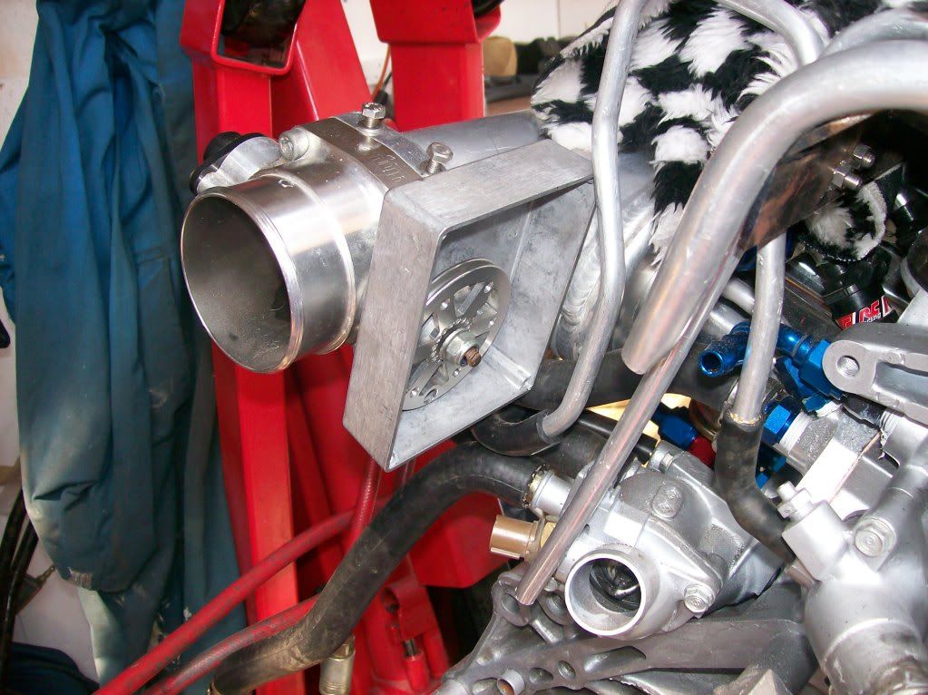
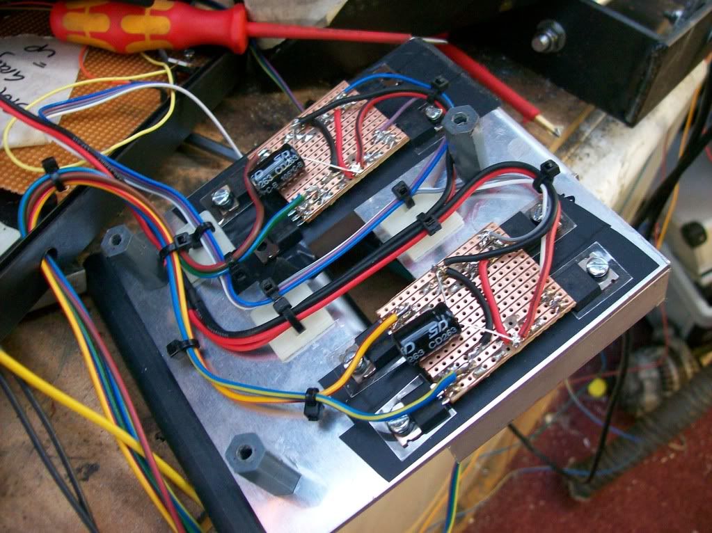
Fixed the h bridge units, sorted a few problems and installed the guide rods... apart from the installation of the covers and the actual control cables, when i can afford them- its done!
I took a video, please excuse the quality.. i had to be careful as the control wires have 36v on them and it would short the h bridges if i connected 2 at the same time... im not very good at one handed camera work lol...
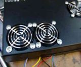
You can see the speed of the motors and almost hear the torque lol... The noise in the background is the cooling fans of the control unit- these are only on whilst the motors are on plus 20 seconds after the motors stop to take care of heat soak..
Fixed the h bridge units, sorted a few problems and installed the guide rods... apart from the installation of the covers and the actual control cables, when i can afford them- its done!
I took a video, please excuse the quality.. i had to be careful as the control wires have 36v on them and it would short the h bridges if i connected 2 at the same time... im not very good at one handed camera work lol...
You can see the speed of the motors and almost hear the torque lol... The noise in the background is the cooling fans of the control unit- these are only on whilst the motors are on plus 20 seconds after the motors stop to take care of heat soak..

Thread Starter
Honda-Tech Member
Joined: Nov 2006
Posts: 573
Likes: 0
From: Preston, Lancashire, United Kingdom
Honda-Tech Member
Joined: Oct 2008
Posts: 357
Likes: 0
From: Rotherham, S Yorks, UK
My moto is to always keep things as simple as possible, so you don't have problems.
You don't... At all, Awesome build/hobby but i'm sure you will be constantly tweaking things. I'm sure this is your aim though. Keep the random additions coming!
You don't... At all, Awesome build/hobby but i'm sure you will be constantly tweaking things. I'm sure this is your aim though.
Keep the random additions coming!

Thread Starter
Honda-Tech Member
Joined: Nov 2006
Posts: 573
Likes: 0
From: Preston, Lancashire, United Kingdom
Thanks chaps, its comments like these that have helped me to keep going with it!!
I used to think the same thing mate, but then i realised, why not! Its part of the enjoyment, fiddling with it and working out bugs..
I used to think the same thing mate, but then i realised, why not! Its part of the enjoyment, fiddling with it and working out bugs..

Thread Starter
Honda-Tech Member
Joined: Nov 2006
Posts: 573
Likes: 0
From: Preston, Lancashire, United Kingdom
Honda-Tech Member
Joined: Oct 2008
Posts: 357
Likes: 0
From: Rotherham, S Yorks, UK
Thread Starter
Honda-Tech Member
Joined: Nov 2006
Posts: 573
Likes: 0
From: Preston, Lancashire, United Kingdom
Hopefully, itll only be improvements at my own lesuire as opposed to getting it working in the first place..

Thread Starter
Honda-Tech Member
Joined: Nov 2006
Posts: 573
Likes: 0
From: Preston, Lancashire, United Kingdom
Thanks mate.. Its not that I want to be different, I just have my own way of doing stuff haha... Whether its the right way or not..
Last edited by purplecivicturbo; Aug 8, 2011 at 09:55 PM.


Thread Starter
Honda-Tech Member
Joined: Nov 2006
Posts: 573
Likes: 0
From: Preston, Lancashire, United Kingdom
Thread Starter
Honda-Tech Member
Joined: Nov 2006
Posts: 573
Likes: 0
From: Preston, Lancashire, United Kingdom
Thanks mate..
It is the kinda thing you pick up over time, but anyone could do it...
That circuit is by no means perfect... In heinseight looking at it, i have a sheet of A4 full of glitches. Things i did wrong .etc
Theyre all correctable, i dont need to remake it- but theyre errors non the less.. Put it this way though- id have a red face now if i had a PCB made!! lol
Honda-Tech Member
Joined: Mar 2003
Posts: 300
Likes: 0
From: Lafayette, LA
I see the resistors, voltage rectifier, and capacitors. I'm not sure why the LED is there, other than to let you know when the board has power, or what the transistors do and why the e-prom bridges are being used.