

Spawne's supercharged B20, sponsored by DDTECH

Thread Starter
Honda-Tech Member
iTrader: (3)
Joined: May 2009
Posts: 5,392
Likes: 1
From: New Jersey
Buddy of mine is making a call tomorrow to get a quote on the work, i talked with a guy last friday about it and he just shook his head no at all the questions i asked him, and he never bothered to call me back. Also talked to Import Performance trans, or as you may know it IPT, and they told me flat out, and I quote "I wont even touch it.".
Honda-Tech Member
Joined: Mar 2012
Posts: 807
Likes: 0
From: Providence, Road Island
4" hole saw, its a bit tricky, because the hole saw was for wood, havent found one made for metal so i just used that, gotta tilt the bit back a slight bit so it doesnt catch the lip of the VC and jam the drill up, but the guide hole has to be drilled right on the edge of the VC bottom. Once you get it going, it eats through that aluminum like butter.
Thread Starter
Honda-Tech Member
iTrader: (3)
Joined: May 2009
Posts: 5,392
Likes: 1
From: New Jersey
Been working on extending the wiring harness in various spots, relocating some wires, and swapping out connectors like my GM 2 bar map sensor. Also finished up with the valve cover. My buddy might airbrush DDTECH into the cover as well if he can get his airbrush working.


Why not go with a vtec head? Don't know if it was already answered. Are you porting the crap out of the stock head?
I'm liking the color choice for the block.
I'm liking the color choice for the block.
Thread Starter
Honda-Tech Member
iTrader: (3)
Joined: May 2009
Posts: 5,392
Likes: 1
From: New Jersey
I kept the non vtec head because I want the powerband to be consistent for a low revving motor, the vtec head port and cam design would push the power up beyond the 8000rpm range, and I dont want to run that on this particular motor with an auto trans. Im looking for peak power somewhere around 7000-7500rpm. The P8R head flows significantly better then the stock LS head because of the increase in valve size from 31 to 33mm. That is where most of the airflow is gained. The ports may not be as elongated as the vtec heads but I dont feel that it will hurt the flow at all.

Thread Starter
Honda-Tech Member
iTrader: (3)
Joined: May 2009
Posts: 5,392
Likes: 1
From: New Jersey
Well this morning my engine fell out....

and before doing that, i decided to do all of this...


found out the coating on my supercharger is GONE, so i have to figure out what im going to do with that, probably just gonna strip it the rest of the way and leave it. Also finished mounting the alternator and testing the new pulley fitment and shimmed as necessary. Gonna finish wrapping the header and mounting the rest of the components to the new engine tonight.


and before doing that, i decided to do all of this...
found out the coating on my supercharger is GONE, so i have to figure out what im going to do with that, probably just gonna strip it the rest of the way and leave it. Also finished mounting the alternator and testing the new pulley fitment and shimmed as necessary. Gonna finish wrapping the header and mounting the rest of the components to the new engine tonight.
Last edited by Spawne32; Jul 27, 2012 at 03:52 PM.

 That DDtech decal goes pretty sweet with it as well.
Honda-Tech Member
Joined: Apr 2008
Posts: 919
Likes: 1
From: Chicago, Illinois, United States
Thread Starter
Honda-Tech Member
iTrader: (3)
Joined: May 2009
Posts: 5,392
Likes: 1
From: New Jersey
thanks, my buddy did all the airbrush work, he thought my original nighthawk black rattle can job looked like crap lol
Honda-Tech Member
Joined: Mar 2007
Posts: 1,116
Likes: 0
From: chester, va, united states
Couldn't you use an automatic civic wither hatch or coupe and have this swap drop right in? That would make sense as long as long as the wiring/mounts are all the same. That is how it is with the manual cars motor mount wise.
Thread Starter
Honda-Tech Member
iTrader: (3)
Joined: May 2009
Posts: 5,392
Likes: 1
From: New Jersey
The civic automatic is physically smaller then the integra transmission, including the internal parts and clutches. While it has the advantage of having an LSD option in one of the japanese m24a versions, it only uses 110mm drums, which makes it less durable then the integra trans. Wiring is completely different as well.


Thread Starter
Honda-Tech Member
iTrader: (3)
Joined: May 2009
Posts: 5,392
Likes: 1
From: New Jersey
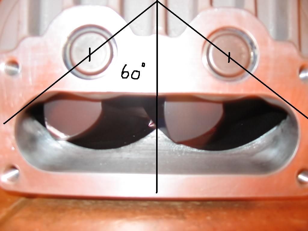
How do you mean match it for the rotor timing? We took an 1/8th of an inch off of each side of the port, cut a 60 degree bevel on the inside and hand filed it to the original shape. I know the timing is critical but working with such small increments i didnt think it would be something I had to worry about?
Thread Starter
Honda-Tech Member
iTrader: (3)
Joined: May 2009
Posts: 5,392
Likes: 1
From: New Jersey
ah ok ill have to double check that tomorrow, any idea if its possible to buy new M45 rotor packs by chance?
no idea could just get it redone Veris had his done i belive with great results
have a read here as i explain the porting in 2 posts
https://honda-tech.com/forums/showth...1#post47534161
have a read here as i explain the porting in 2 posts
https://honda-tech.com/forums/showth...1#post47534161
Thread Starter
Honda-Tech Member
iTrader: (3)
Joined: May 2009
Posts: 5,392
Likes: 1
From: New Jersey
no idea could just get it redone Veris had his done i belive with great results
have a read here as i explain the porting in 2 posts
https://honda-tech.com/forums/showth...1#post47534161
have a read here as i explain the porting in 2 posts
https://honda-tech.com/forums/showth...1#post47534161
I havent done anything to the inlet but like the outlet, its got tons of casting flaws just coated with teflon.
I did my porting and anothers freehand
after you have aligned the rotors and scribed the rotor alignmet you will find its not to hard
you will also notice to that the outlet has a very soft S shape to it its not a straight V this is to match the twist of the rotor edge
the reason for timming before porting is when the rotor in at 60deg inlet that side of the charger is now a sealed chamber full
of air so you want it to release it just after that at the opening/outlet allowing 1mm from the rotor blade to the outlet edge
doing this will cause the rotor to take its full amount of air and discharge it soon after
think of it like a combustion chamber
the total effect is more air moved with less delay raising your cfm and taking a lot of heat out of the rotor pack
with the inlet its the oposite
with the rotor at 60deg you can see the gap to the next rotor of that side
being the floor of the charger housing
this can bee opened up and smoothed out to allow as much air as possible to fill it before it seals
if you loook at the pic above you can see that the floor has been soothed deep into it to allow air into the swept area
oh and re the teflon all three i have worked on have been stripped out and hand polished with a ultra fine metal polish
Thread Starter
Honda-Tech Member
iTrader: (3)
Joined: May 2009
Posts: 5,392
Likes: 1
From: New Jersey
Doing yours freehand were you able to maintain that slight S shape? As far as we could tell there was nothing special about the shape of this outlet, other then how shitty it was. We did check for any sort of special shape to it and IMO there was nothing of significance in this particular cast. The blower case on the inside where the rotors spin is full of pits and holes from a porous air filled sand cast, the whole thing was completely uneven and had to be skim cut to even sit level on the mill and the outlet was so uneven from front to back we couldnt even get a measurement on it. I had been comparing port work from various "proffesionals" for the past month and ive seen some pretty bad hand ports that still made boost with no issues so i felt we did a damn fine job on the thing compared with what i started with.


in regards to the porting I spent a lot of hours talking to pro's in the drag racing game
to learn the black arts of charger porting
even as far as to polish and not to polish the porting work
one engine builder showed me a cad flow movie on how the flow works on a root type charger and explained how to improve it and then show the effects of each modification
( I did spend four years in research before doing my jrsc build)
alot of the pits you describe would be damage from crap comming from the air filter
as far as the rotor striping Ive found if you carefully brush on paint striper you can get it of with out damaging the bearing seals at the gear end
when ive striped a few ive left the teflon alone between the rotor to gear case as it wont hurt it at all