

resistor box wiring....

Thread Starter
Honda-Tech Member
Joined: Oct 2007
Posts: 1,316
Likes: 0
From: Greenville, SC, usa
i tried searching for it and im sure its out there but i couldnt find it...can some one explain or point me in the right direction for the wiring diagram on the resistor box...thanks
Honda-Tech Member
Joined: Apr 2001
Posts: 16,905
Likes: 3
From: Lansdale, PA
for the record. the links you are looking for are conviently located of the Forced Induction forum, Labled ***Forced Induction Forum FAQ***
what you need to do is find the 4 yel blk wires coming from the dead end plug to the injectors, those 4 wires will connect to the 4 blk wires on the resistor box, the red wire, then goes into the dead end connector, and thats it.
what you need to do is find the 4 yel blk wires coming from the dead end plug to the injectors, those 4 wires will connect to the 4 blk wires on the resistor box, the red wire, then goes into the dead end connector, and thats it.
Thread Starter
Honda-Tech Member
Joined: Oct 2007
Posts: 1,316
Likes: 0
From: Greenville, SC, usa
thanks man....  only thing is i have 4 black and a red wire but then it has a plug that is pluged in and there are 4 red wires and a yellow....do i just supstitute the red for black and the yellow for the red....this is on my resistor box...
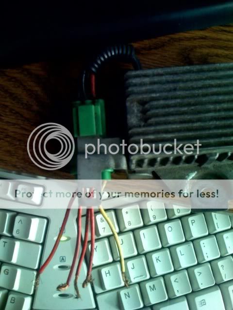
see what i mean?
only thing is i have 4 black and a red wire but then it has a plug that is pluged in and there are 4 red wires and a yellow....do i just supstitute the red for black and the yellow for the red....this is on my resistor box...see what i mean?
Honda-Tech Member
Joined: May 2003
Posts: 5,735
Likes: 0
From: Portland, Oregon
<TABLE WIDTH="90%" CELLSPACING=0 CELLPADDING=0 ALIGN=CENTER><TR><TD>Quote, originally posted by T9U4ReBgO »</TD></TR><TR><TD CLASS="quote">thanks man.... only thing is i have 4 black and a red wire but then it has a plug that is pluged in and there are 4 red wires and a yellow....do i just supstitute the red for black and the yellow for the red....this is on my resistor box...</TD></TR></TABLE>
Yes, the 4 wires that are the same color go to the injectors, and the one other goes to the ecu side.
only thing is i have 4 black and a red wire but then it has a plug that is pluged in and there are 4 red wires and a yellow....do i just supstitute the red for black and the yellow for the red....this is on my resistor box...</TD></TR></TABLE>Yes, the 4 wires that are the same color go to the injectors, and the one other goes to the ecu side.

Honda-Tech Member
Joined: May 2002
Posts: 3,448
Likes: 0
From: Illanoise, USA
This is one I did 4.5 years ago+. There are others out there.
https://honda-tech.com/zerothread?id=517274
https://honda-tech.com/zerothread?id=517274
Trending Topics
Honda-Tech Member
Joined: May 2007
Posts: 599
Likes: 1
From: Gilroy, Ca, USA
The Offical No-Brainer Resistor Box Install
What you will need:
Razor blade
Electrical Tape; Shrink tubing won't work unless you cut the harness wires.
Soldering Iron+solder, etc.
Resistor Box
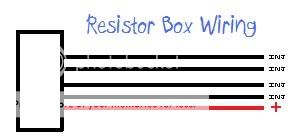
F.Y.I. 99% of resistor boxes with 5 wires have 4 identical colored and one off colored. The off colored would be the + wire.
Take your stock plug, and uncover the wires for a short bit so they are exposed.
Unplug the dummy plug and set aside. You will want 2 of these, you will understand this later.
Turn the ignition on, but leave the motor off.
Using a multimeter, check each of the pins on the connector the plug came out of untill you find +12V. Note this wire (write it down) or flag the wire with a tape note.
Now, turn the ignition off, and unplug the plugs from the injectors. These plugs each have a yellow wire going to them. Using an ohmmeter or a continuity checker, find which 4 wires from the connector the dummy plug was in lead to the injectors. Note these on paper or flag them off.
Now, you can seperate out the + wire from the harness (away from the injector and sensor wires) and using a razor blade; carefully cut the plastic sleeving [around 1" or so from the connector) around the wire but not into the wire, once you have made one cut, move about 1/3-1/2" farther and make another cut. then make a cut lengthwise joining them, this will split it open, and the wire will be missing it's protective sleeve. Now, take the + wire from the resistor box, and hook it up to the + wire on the harness by wraping the resistor box wire around the + wire on the harness. Solder and tape it securely.
Follow this procedure for the remaining injector wires.

Now is the fun part; If you put the dummy plug back in, the resistor box is being bypassed by the dummy plug; This is the Stock configuration you would use if you had to lets say; revert back to smog your car.
Refer to my picture, and verify with your notes to make sure you cut the right pins out, but take your second connector, and using needle nose pliers, reach down in on the pins for the injector wires, grasp firmly, and twist slightly while rocking; resist pulling hard as it could damage the rest of the connector. When your done it _should_ look like this if your engine harness has the same layout as mine;

This is your resistored plug.
What you will need:
Razor blade
Electrical Tape; Shrink tubing won't work unless you cut the harness wires.
Soldering Iron+solder, etc.
Resistor Box
F.Y.I. 99% of resistor boxes with 5 wires have 4 identical colored and one off colored. The off colored would be the + wire.
Take your stock plug, and uncover the wires for a short bit so they are exposed.
Unplug the dummy plug and set aside. You will want 2 of these, you will understand this later.
Turn the ignition on, but leave the motor off.
Using a multimeter, check each of the pins on the connector the plug came out of untill you find +12V. Note this wire (write it down) or flag the wire with a tape note.
Now, turn the ignition off, and unplug the plugs from the injectors. These plugs each have a yellow wire going to them. Using an ohmmeter or a continuity checker, find which 4 wires from the connector the dummy plug was in lead to the injectors. Note these on paper or flag them off.
Now, you can seperate out the + wire from the harness (away from the injector and sensor wires) and using a razor blade; carefully cut the plastic sleeving [around 1" or so from the connector) around the wire but not into the wire, once you have made one cut, move about 1/3-1/2" farther and make another cut. then make a cut lengthwise joining them, this will split it open, and the wire will be missing it's protective sleeve. Now, take the + wire from the resistor box, and hook it up to the + wire on the harness by wraping the resistor box wire around the + wire on the harness. Solder and tape it securely.
Follow this procedure for the remaining injector wires.
Now is the fun part; If you put the dummy plug back in, the resistor box is being bypassed by the dummy plug; This is the Stock configuration you would use if you had to lets say; revert back to smog your car.
Refer to my picture, and verify with your notes to make sure you cut the right pins out, but take your second connector, and using needle nose pliers, reach down in on the pins for the injector wires, grasp firmly, and twist slightly while rocking; resist pulling hard as it could damage the rest of the connector. When your done it _should_ look like this if your engine harness has the same layout as mine;
This is your resistored plug.

Thread
Thread Starter
Forum
Replies
Last Post