

Official Injector Resistor Box Install......56k, Buy Broadband.

Thread Starter
Honda-Tech Member
Joined: May 2002
Posts: 3,448
Likes: 0
From: Illanoise, USA
I have never really seen an "Official" injector box install with pictures, so I went ahead and did it yesterday to make it easier for others trying to do this. Pictures say MORE than a thousand words sometimes. 
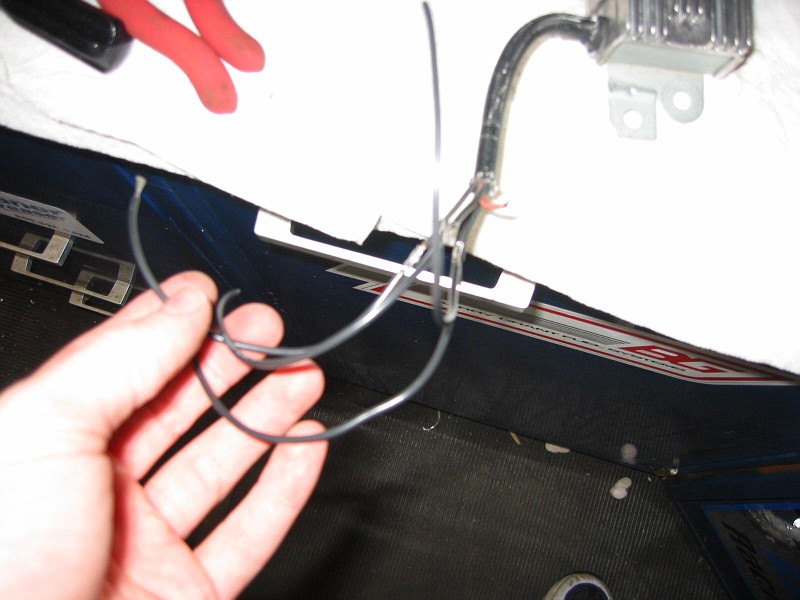
First step is to check continuity. I was just going to use Hondata's site but am I glad I didn't!!! Mine was completely different from what their site said. You will then cut these wires about 1 inch from the distribution block.

Next step is to splice the wires on the injector box itself to prepare for soldering.
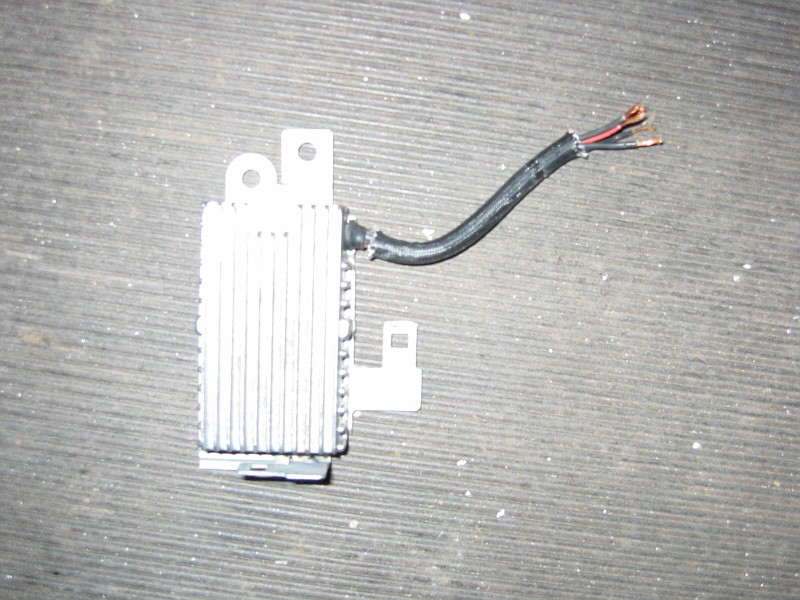
Step 3 is too solder extra wire onto the injector box. I had to do this because of where I was mounting it.
Step for is to make it nice and neat when done soldering. I used heat shrink tubing that I snagged from a buddy at a local stereo shop. Thanks Tobster!!
Step 5 is to wire all 4 wires of the distribution block together (These wires are the one you tested in step 1) and solder the red wire to them.

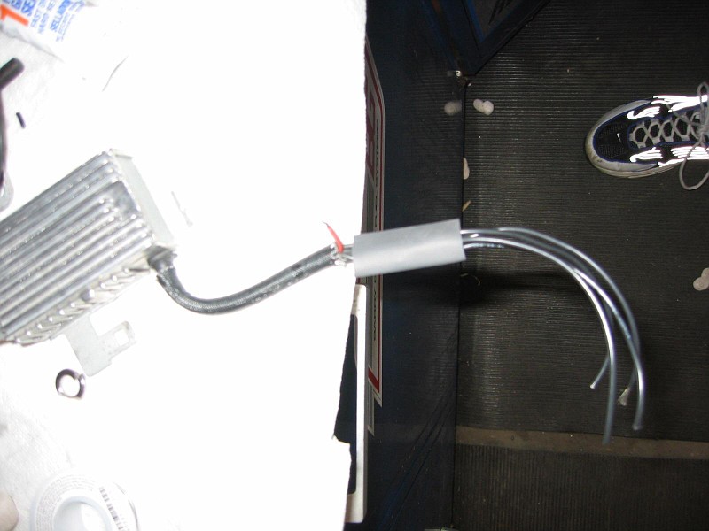
Step 6 is to wire the black wires to the 4 yellow and black wires on the harness side. I heat shrank mine when I was done to make it neat again.

Step 7 is to find a place to mount it. I mounted mine on a already tapped 10mm hole right by the clutch master cylinder. Here it is ready to be mounted.

Another couple of shots completed.


Hope everyone finds this useful information. Sorry about all the pictures but sometimes you just have to in order to get a point across.
Enjoy!
Modified by ladysman at 6:50 AM 5/28/2003
First step is to check continuity. I was just going to use Hondata's site but am I glad I didn't!!! Mine was completely different from what their site said. You will then cut these wires about 1 inch from the distribution block.
Next step is to splice the wires on the injector box itself to prepare for soldering.
Step 3 is too solder extra wire onto the injector box. I had to do this because of where I was mounting it.
Step for is to make it nice and neat when done soldering. I used heat shrink tubing that I snagged from a buddy at a local stereo shop. Thanks Tobster!!
Step 5 is to wire all 4 wires of the distribution block together (These wires are the one you tested in step 1) and solder the red wire to them.
Step 6 is to wire the black wires to the 4 yellow and black wires on the harness side. I heat shrank mine when I was done to make it neat again.
Step 7 is to find a place to mount it. I mounted mine on a already tapped 10mm hole right by the clutch master cylinder. Here it is ready to be mounted.
Another couple of shots completed.
Hope everyone finds this useful information. Sorry about all the pictures but sometimes you just have to in order to get a point across.
Enjoy!
Modified by ladysman at 6:50 AM 5/28/2003
Last edited by ladysman; Dec 28, 2008 at 11:02 AM. Reason: Updated Photo Locations because of Multiple Requests
Honda-Tech Member
Joined: Jun 2002
Posts: 5,551
Likes: 1
From: USA
I bought broadband... woohoooo. ok enough of that.
nice write up and clean install... I hate the ghetto restistor looking setups.
nice write up and clean install... I hate the ghetto restistor looking setups.
Honda-Tech Member
Joined: Jun 2001
Posts: 2,763
Likes: 2
From: Dark Aether
Good job.

FYI though, that power distribution block was not present on my 2000 Civic Si. I saw something that looked liked it on the bottom side of the intake manifold (ie, impossible to work on). I don't think OBD2 Civics have that plug in a place that is accessable like yours.
Sonny
Thread Starter
Honda-Tech Member
Joined: May 2002
Posts: 3,448
Likes: 0
From: Illanoise, USA
<TABLE WIDTH="90%" CELLSPACING=0 CELLPADDING=0 ALIGN=CENTER><TR><TD>Quote, originally posted by Sonny »</TD></TR><TR><TD CLASS="quote">
Good job.
FYI though, that power distribution block was not present on my 2000 Civic Si. I saw something that looked liked it on the bottom side of the intake manifold (ie, impossible to work on). I don't think OBD2 Civics have that plug in a place that is accessable like yours.
Sonny</TD></TR></TABLE>
Thanks for your help on the injector clips!!!
Honda-Tech Member
Joined: Oct 2001
Posts: 347
Likes: 0
From: some crappy place in, wa, usa
For EKs there is a similar plug underneath the intake manifold where you can tap into these wires.
Trending Topics
Thread Starter
Honda-Tech Member
Joined: May 2002
Posts: 3,448
Likes: 0
From: Illanoise, USA
<TABLE WIDTH="90%" CELLSPACING=0 CELLPADDING=0 ALIGN=CENTER><TR><TD>Quote, originally posted by integranator »</TD></TR><TR><TD CLASS="quote">oh lord...i think i've been running my resistor box wired wrong... What kind of damage would Occur from this?! </TD></TR></TABLE>
ECU frying I would guess.
ECU frying I would guess.
Thread Starter
Honda-Tech Member
Joined: May 2002
Posts: 3,448
Likes: 0
From: Illanoise, USA
<TABLE WIDTH="90%" CELLSPACING=0 CELLPADDING=0 ALIGN=CENTER><TR><TD>Quote, originally posted by integranator »</TD></TR><TR><TD CLASS="quote">ok, so I looked at my wiring, and it possibly might not be wrong--- if my ecu fried I would know it, right?</TD></TR></TABLE>
Yeah, I would think you could know it almost instantly. Never had it happen so I can't tell you for sure.
Yeah, I would think you could know it almost instantly. Never had it happen so I can't tell you for sure.
Member
Joined: Oct 2002
Posts: 3,279
Likes: 0
From: Secret Tweaker Pad
<TABLE WIDTH="90%" CELLSPACING=0 CELLPADDING=0 ALIGN=CENTER><TR><TD>Quote, originally posted by H23vtecEG »</TD></TR><TR><TD CLASS="quote">what are those wires that you tapped in to that plug where the resistor is now located, the wires that go in the fire wall? </TD></TR></TABLE>
wires that go to the injectors
wires that go to the injectors

Joined: Dec 2002
Posts: 1,506
Likes: 1
From: manchester, nh, us
nooo not that the big plug at the end is tapped right, you know the plug that was tapped for the resistor to go in. this plug at the end is blocked and wires lead no where, we all know that.
now at the end of this blocked plug there is another smaller plug that has wires that lead into the firewall. is that smaller plug lead in to a 12v power source?, or just putting the end of the ye/blk wires together with the red wire give me the power source.
i know i can go to the end of the pug and wire the resistor there, just cut the wires at the end of the plug and put resistor between them. is that alllllll or do i have to tap somewhere else for a switched 12v source.
Thread Starter
Honda-Tech Member
Joined: May 2002
Posts: 3,448
Likes: 0
From: Illanoise, USA
<TABLE WIDTH="90%" CELLSPACING=0 CELLPADDING=0 ALIGN=CENTER><TR><TD>Quote, originally posted by H23vtecEG »</TD></TR><TR><TD CLASS="quote">nooo not that the big plug at the end is tapped right, you know the plug that was tapped for the resistor to go in. this plug at the end is blocked and wires lead no where, we all know that.
now at the end of this blocked plug there is another smaller plug that has wires that lead into the firewall. is that smaller plug lead in to a 12v power source?, or just putting the end of the ye/blk wires together with the red wire give me the power source.
i know i can go to the end of the pug and wire the resistor there, just cut the wires at the end of the plug and put resistor between them. is that alllllll or do i have to tap somewhere else for a switched 12v source. </TD></TR></TABLE>
You have lost me completely. You don't need a power source for the resistor pack.
Nice to see this post is back from the dead though.
Joined: Mar 2002
Posts: 3,281
Likes: 0
Just curious how yours was different than the hondata site?I did mine the hondata way and my car hesitates,possibly because it might be different.
Thread Starter
Honda-Tech Member
Joined: May 2002
Posts: 3,448
Likes: 0
From: Illanoise, USA
<TABLE WIDTH="90%" CELLSPACING=0 CELLPADDING=0 ALIGN=CENTER><TR><TD>Quote, originally posted by J2turbo21 »</TD></TR><TR><TD CLASS="quote">Just curious how yours was different than the hondata site?I did mine the hondata way and my car hesitates,possibly because it might be different.</TD></TR></TABLE>
The pinouts were different than what was on Hondata's site.
The pinouts were different than what was on Hondata's site.