

DIY: H22A VALVE ADJUSTMENT

Thread Starter
space cadet
Joined: Nov 2002
Posts: 6,091
Likes: 0
From: Spec Shakesland
-Disclamer-
I am not a professional. Any and all happenings good or bad are completely up to the user of this DIY write up. This is exactly what I did on my 2000 SH and it worked great. If you so choose to use this write up I am in no way responsible for any outcome that may occour.
DIY H22A Valve Adjustment
Tools required-
10mm deep well socket
10mm wrench
19mm deep well socket
Spark plug socket
6" extention
Rachet
Vise grips (optional. I used them)
Medium Flat tip screw driver
Pliers (depending on what type of clamps you have on your hoses going to the valve cover)
Torque wrench (14 lb ft or 168 lb in )
Angled feeler gauge (.006, .007, .008) For those that need further explanation .005 is intake low; .006 is intake high; .007 is exhaust low; .008 is exhaust high. recommend using .006 for intake, .007 to check, and .008 for exhaust with .009 to check
-friends to help. thanks Sam (boosted97lude) and Grant!
Very important
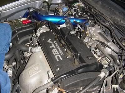
Make sure that your engine is cold. I let my car sit for just over three hours before starting. I had only driven it 5 miles to the shop. When I began removing parts it was still too warm to do the adjustment. I would suggest that if it isnt cold, not luke warm but cold, that you do not do this procedure. Wait until it is cold.
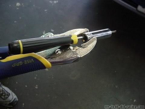
Snap-on corp makes a tool specifically for honda. This tool is used for valve adjustments and valve adjustments only. I did not use this tool. I made my own. If you would like to it is easy. All you will need is a pair of Vise-grips, a 10mm deep well socket, and a flat head screwdriver that will fit through the hole of the socket.
Angle the vice grips at apx. 80 degrees when you clamp it to the 10mm socket. Stick the screw driver through the socket and there you go. You just scarred up a perfectly good socket but saved $40.
procedure
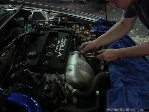
-start by removing the spark plug cover. Use the 10mm socket for this.
- remove the spark plug wires and place them off to the side. Make sure to keep the terminals clean.
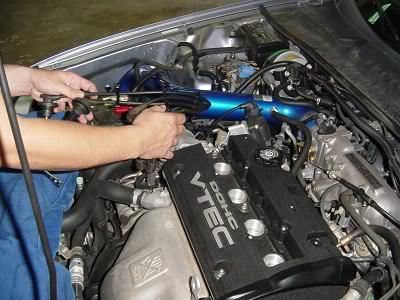
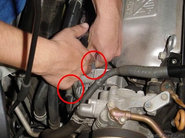
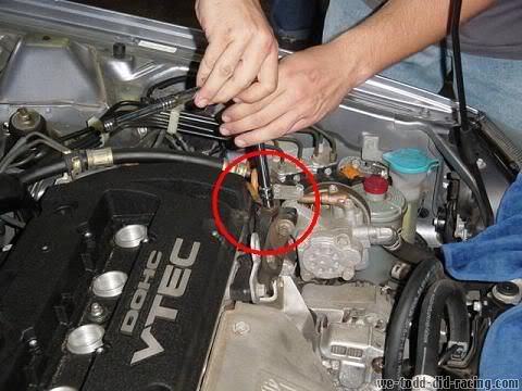
- the alternator wires run along top of the valve cover and will need to be removed. Start by taking off the bolt attatching the wire harness to the front of the valve cover. Once again using the 10mm socket.
- next remove the plug and nut on the alternator. The plug has one snap on it and the nit is also a 10mm. You may want to pull back the rubber cover to get better access to it.
- the wiring harness has a plastic clip attaching it as well. You can use your hand to pull it off or a small flat head screw driver to pry it off.
- finally for the wiring harness remove the upper bolt. Attached to the rear of the valve cover. Use the 10mm socket for this.
- once you have removed all attaching hardware for the wiring harness carefully lift and place behind the engine ontop of the intake manifold.
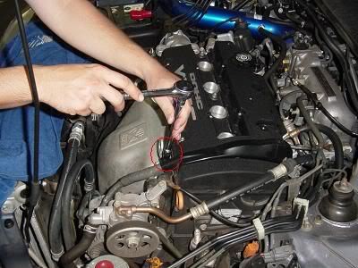
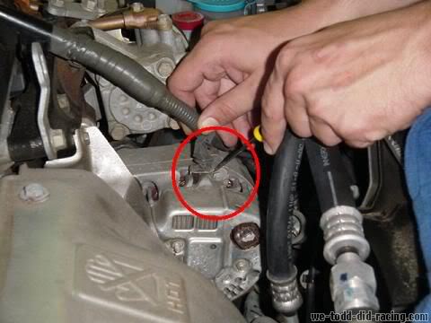
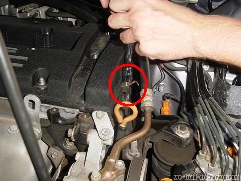
- next there is a ground wire that will need to be removed. This is on the drivers side of the car and will use the 10mm socket.
- there is another grounding strap that will need to be removed. It is in the close proximity to the one just removed. It will use the 10mm socket as well
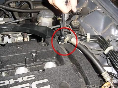
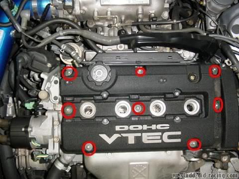
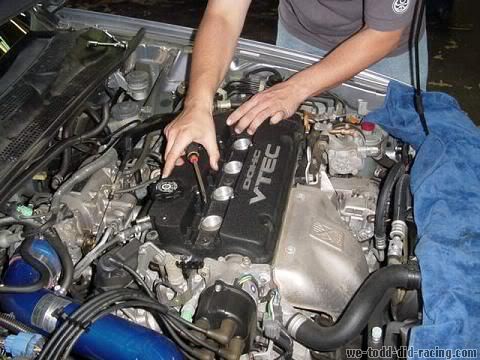
- On to the Valve cover. There are 8 round top nuts that will need to be removed.
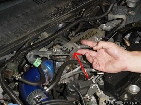
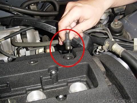
- next remove the PVC plug
- there is only one hose left. That will be going from your intake to the valve cover. I did not get a picture of it but depending on the type of clamp you have there you will want to use either a socket, flat head screwdriver, or a pair of pliers.
- now you are ready to remove the valve cover. Place your flat head screwdriver in between the head and the valve cover. Gently pry it loose. If you are careful you will be able to reuse the same seal over and over again. Just remember to re oil it before replacing.
- once the valve cover is loose you can remove it. Do not set it down on its seal. Place it seal up to keep it clean and free of debris.
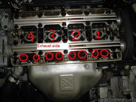
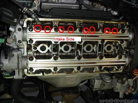
- now you should be looking at the top of your head. On the exhaust manifold/header side is the exhaust cam. The intake manifold side is the intake cam. There are 8 valves per side. 16 total. Each valve has a set screw/lock nut which you will use your special tool or wrench and screw driver and torque wrench to adjust.
- Now it is time to remove the spark plugs. You do not have to but it does help to relieve pressure in the engine and I would highly suggest it.
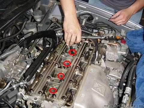
- go to each valve and loosen the lock nuts. Use a 10mm socket for this.

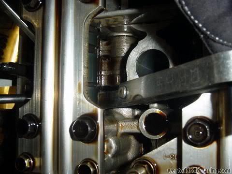
- while doing this adjustment it is very important that the valves be closed. To make certian that they are closed set the cam you are working on to show the lobe looking at you.
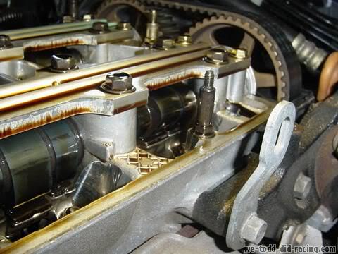
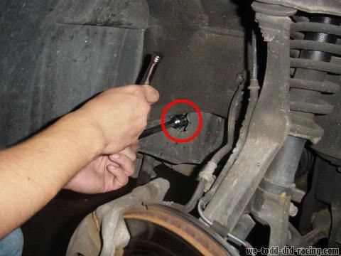
To do this you will need to turn the crank manually. Remove the drivers side front tire and you will see a hole. It is just big enough to place your 19mm socket in. You will need the 6'' extention for this. Turn the crank COUNTER CLOCKWISE. It may take some brute force at times, just remember what you are turning. Its not light weight so put your shoulder into it. Stop when you can see that the lobe is facing any direction but down or at a downward angle. You will need to repeat this step for each set of valves. Both intake and exhaust. It does get tedious but it is precise.
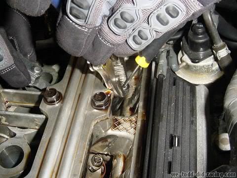
- now it is time to start the actual adjustment. To do the actual adjustment you will need to use your feeler gauge and your ghetto fab tool or wrench and screwdriver. Unless you spent the $40 on the correct tool. You should feel drag on the feeler gauge when it is at the correct setting. Move the feeler gauge in and out while your shop partner tightens/loosens the set screw. When it gets tight but still movable set the locknut. Make sure that when you have the correct valve lash set that you do NOT move the screwdriver at all while you tighten the locknut.
The way that I made sure that I had the correct ammount of play was to use the low side. As an example on the intake side I used the .006 for the setting. When I felt that I had it correct we would set the locknut. I would then take the .007 and check to make sure it did not fit in. If the .006 fit and the .007 did not we would torque the locknut to 14 lb ft and then check again. If nothing moved we moved to the next valve. You may have to repeat this multiple times per valve to get it just right.
Once you have completed the adjustment go over everything once again. Check all lash clearances to make sure nothing has moved. If it did; redo it.
Once everything is set and good to go replace all parts in reverse order.your car should be withing specs now and running smoother.
Hope this helped. if anyone has any additions/corrections please let me know.
I am not a professional. Any and all happenings good or bad are completely up to the user of this DIY write up. This is exactly what I did on my 2000 SH and it worked great. If you so choose to use this write up I am in no way responsible for any outcome that may occour.
DIY H22A Valve Adjustment
Tools required-
10mm deep well socket
10mm wrench
19mm deep well socket
Spark plug socket
6" extention
Rachet
Vise grips (optional. I used them)
Medium Flat tip screw driver
Pliers (depending on what type of clamps you have on your hoses going to the valve cover)
Torque wrench (14 lb ft or 168 lb in )
Angled feeler gauge (.006, .007, .008) For those that need further explanation .005 is intake low; .006 is intake high; .007 is exhaust low; .008 is exhaust high. recommend using .006 for intake, .007 to check, and .008 for exhaust with .009 to check
-friends to help. thanks Sam (boosted97lude) and Grant!
Very important
Make sure that your engine is cold. I let my car sit for just over three hours before starting. I had only driven it 5 miles to the shop. When I began removing parts it was still too warm to do the adjustment. I would suggest that if it isnt cold, not luke warm but cold, that you do not do this procedure. Wait until it is cold.
Snap-on corp makes a tool specifically for honda. This tool is used for valve adjustments and valve adjustments only. I did not use this tool. I made my own. If you would like to it is easy. All you will need is a pair of Vise-grips, a 10mm deep well socket, and a flat head screwdriver that will fit through the hole of the socket.
Angle the vice grips at apx. 80 degrees when you clamp it to the 10mm socket. Stick the screw driver through the socket and there you go. You just scarred up a perfectly good socket but saved $40.
procedure
-start by removing the spark plug cover. Use the 10mm socket for this.
- remove the spark plug wires and place them off to the side. Make sure to keep the terminals clean.
- the alternator wires run along top of the valve cover and will need to be removed. Start by taking off the bolt attatching the wire harness to the front of the valve cover. Once again using the 10mm socket.
- next remove the plug and nut on the alternator. The plug has one snap on it and the nit is also a 10mm. You may want to pull back the rubber cover to get better access to it.
- the wiring harness has a plastic clip attaching it as well. You can use your hand to pull it off or a small flat head screw driver to pry it off.
- finally for the wiring harness remove the upper bolt. Attached to the rear of the valve cover. Use the 10mm socket for this.
- once you have removed all attaching hardware for the wiring harness carefully lift and place behind the engine ontop of the intake manifold.
- next there is a ground wire that will need to be removed. This is on the drivers side of the car and will use the 10mm socket.
- there is another grounding strap that will need to be removed. It is in the close proximity to the one just removed. It will use the 10mm socket as well
- On to the Valve cover. There are 8 round top nuts that will need to be removed.
- next remove the PVC plug
- there is only one hose left. That will be going from your intake to the valve cover. I did not get a picture of it but depending on the type of clamp you have there you will want to use either a socket, flat head screwdriver, or a pair of pliers.
- now you are ready to remove the valve cover. Place your flat head screwdriver in between the head and the valve cover. Gently pry it loose. If you are careful you will be able to reuse the same seal over and over again. Just remember to re oil it before replacing.
- once the valve cover is loose you can remove it. Do not set it down on its seal. Place it seal up to keep it clean and free of debris.
- now you should be looking at the top of your head. On the exhaust manifold/header side is the exhaust cam. The intake manifold side is the intake cam. There are 8 valves per side. 16 total. Each valve has a set screw/lock nut which you will use your special tool or wrench and screw driver and torque wrench to adjust.
- Now it is time to remove the spark plugs. You do not have to but it does help to relieve pressure in the engine and I would highly suggest it.
- go to each valve and loosen the lock nuts. Use a 10mm socket for this.
- while doing this adjustment it is very important that the valves be closed. To make certian that they are closed set the cam you are working on to show the lobe looking at you.
To do this you will need to turn the crank manually. Remove the drivers side front tire and you will see a hole. It is just big enough to place your 19mm socket in. You will need the 6'' extention for this. Turn the crank COUNTER CLOCKWISE. It may take some brute force at times, just remember what you are turning. Its not light weight so put your shoulder into it. Stop when you can see that the lobe is facing any direction but down or at a downward angle. You will need to repeat this step for each set of valves. Both intake and exhaust. It does get tedious but it is precise.
- now it is time to start the actual adjustment. To do the actual adjustment you will need to use your feeler gauge and your ghetto fab tool or wrench and screwdriver. Unless you spent the $40 on the correct tool. You should feel drag on the feeler gauge when it is at the correct setting. Move the feeler gauge in and out while your shop partner tightens/loosens the set screw. When it gets tight but still movable set the locknut. Make sure that when you have the correct valve lash set that you do NOT move the screwdriver at all while you tighten the locknut.
The way that I made sure that I had the correct ammount of play was to use the low side. As an example on the intake side I used the .006 for the setting. When I felt that I had it correct we would set the locknut. I would then take the .007 and check to make sure it did not fit in. If the .006 fit and the .007 did not we would torque the locknut to 14 lb ft and then check again. If nothing moved we moved to the next valve. You may have to repeat this multiple times per valve to get it just right.
Once you have completed the adjustment go over everything once again. Check all lash clearances to make sure nothing has moved. If it did; redo it.
Once everything is set and good to go replace all parts in reverse order.your car should be withing specs now and running smoother.
Hope this helped. if anyone has any additions/corrections please let me know.
Last edited by Shakes; Jul 26, 2009 at 02:37 PM.


Thread Starter
space cadet
Joined: Nov 2002
Posts: 6,091
Likes: 0
From: Spec Shakesland
<TABLE WIDTH="90%" CELLSPACING=0 CELLPADDING=0 ALIGN=CENTER><TR><TD>Quote, originally posted by del_parker »</TD></TR><TR><TD CLASS="quote">why didn't you just use a wrench and screwdriver instead of vise grips, socket, and screwdriver? is the obstruction really that bad?</TD></TR></TABLE>
the wrench and screw driver method is ok but you cant really get the locknut tight enough and then when you go to torque it down the set screw may close up even more. resulting in you having to redo the entire valve. we bent a box end wrench and that worked ok, but we couldnt move it enough each time. that is why we went with the ghetto fab tool.
the wrench and screw driver method is ok but you cant really get the locknut tight enough and then when you go to torque it down the set screw may close up even more. resulting in you having to redo the entire valve. we bent a box end wrench and that worked ok, but we couldnt move it enough each time. that is why we went with the ghetto fab tool.
Trending Topics


Senior Member
Joined: May 2001
Posts: 10,753
Likes: 1
From: Where snow is, I am.
Very nice write up!
I don't remember off hand, what what is the exaact feeler gauge measure ment for the exhaust and the intake. I believe it.s .006" for the exhaust (which you stated above), and .007 or or .008 but I am not sure.
Another thing as well to point out....
INSTEAD of checking the cam to see if that specific cylinder, just simply look at the cam gears to ensure you do the valve adjustment in order..
You want to adjust Cylinder 1, then 3, then 4, then 2 in firing order.
Here is a ghetto diagram I just made:

HTH
I don't remember off hand, what what is the exaact feeler gauge measure ment for the exhaust and the intake. I believe it.s .006" for the exhaust (which you stated above), and .007 or or .008 but I am not sure.
Another thing as well to point out....
INSTEAD of checking the cam to see if that specific cylinder, just simply look at the cam gears to ensure you do the valve adjustment in order..
You want to adjust Cylinder 1, then 3, then 4, then 2 in firing order.
Here is a ghetto diagram I just made:
HTH

Honda-Tech Member
Joined: Jun 2001
Posts: 590
Likes: 0
From: Tampa, FL, USA
I made a very good ghetto adjustment tool by welding two deep 10mm sockets on top of each other and a long a/c bolt welded to the side to apply torque. A long screwdriver fits through. I've used this same tool for over four years and a prefer it to the actual honda tool.
Thread Starter
space cadet
Joined: Nov 2002
Posts: 6,091
Likes: 0
From: Spec Shakesland
that is the "proper" way to do that. thanks poison. the only reason i didnt was because i am a fat lazy bastard and didnt want to take off that bottom cover thing to see the marks lol.
Member
Joined: Jul 2001
Posts: 2,392
Likes: 0
From: Chandler, AZ, USA
I dont think that diagram helps at all.
At the "real" TDC, the lobes are still fairly close to the rockers. I do an extra little turn after the TDC mark to get the lobes completely "out" from the rockers, making sure that no lift on the cam lobe can come into play.
Also....when an intake shows TDC, one exhaust will also be TDC, so do them both. I dont like the method of doing all the intake first, then all the exhaust. Just make sure you switch the feeler gauges you use and you'll save quite a bit of time.
Senior Member
Joined: May 2001
Posts: 10,753
Likes: 1
From: Where snow is, I am.
haha, just trying to help. It's best if it's done in the right order and fastest.
You mean to tell me that you took all those bad *** pics and claim yourself as "lazy?


You mean to tell me that you took all those bad *** pics and claim yourself as "lazy?
Senior Member
Joined: May 2001
Posts: 10,753
Likes: 1
From: Where snow is, I am.
<TABLE WIDTH="90%" CELLSPACING=0 CELLPADDING=0 ALIGN=CENTER><TR><TD>Quote, originally posted by 4bidden »</TD></TR><TR><TD CLASS="quote">I dont think that diagram helps at all.
At the "real" TDC, the lobes are still fairly close to the rockers. I do an extra little turn after the TDC mark to get the lobes completely "out" from the rockers, making sure that no lift on the cam lobe can come into play.</TD></TR></TABLE>
Yeah, I was merely showing the proper order, and the setting on the factory cam gears with the arrows pointing. That is the correct method making sure everything is at TDC. As far as 'moving' it a little, to get them off the rockers, that's a little extra, and a good pointer.
<TABLE WIDTH="90%" CELLSPACING=0 CELLPADDING=0 ALIGN=CENTER><TR><TD>Quote, originally posted by 4bidden »</TD></TR><TR><TD CLASS="quote">Also....when an intake shows TDC, one exhaust will also be TDC, so do them both. I dont like the method of doing all the intake first, then all the exhaust. Just make sure you switch the feeler gauges you use and you'll save quite a bit of time.</TD></TR></TABLE>
Yes, as I would do the same way. Saves a lot of time
Thread Starter
space cadet
Joined: Nov 2002
Posts: 6,091
Likes: 0
From: Spec Shakesland
<TABLE WIDTH="90%" CELLSPACING=0 CELLPADDING=0 ALIGN=CENTER><TR><TD>Quote, originally posted by MoogenTypeS »</TD></TR><TR><TD CLASS="quote">I just did my valves and it kind of seems worse to me. I don't know what to do.... </TD></TR></TABLE>
print the instructions i wrote. then do them. as long as its an H22a of course.
print the instructions i wrote. then do them. as long as its an H22a of course.
Joined: Oct 2003
Posts: 8
Likes: 0
From: San Jose, CA
and any suggestions for getting off a valve cover bolt? the thread seems to have been stripped when trying to remove the valve cover and it won't even budge! it keeps spinning and spinning and spinning....  Thanks.
Thanks.
Joined: Oct 2003
Posts: 1
Likes: 0
From: Tampa Bay, Fl, USA
You might want to add a first step to your list of
Disconnect negative battery terminal from battery.
Might save someone their wiring harness.
Granted, you don't _have_ to, but I would.
Regards,
Mike M.
Disconnect negative battery terminal from battery.
Might save someone their wiring harness.
Granted, you don't _have_ to, but I would.
Regards,
Mike M.

Thread Starter
space cadet
Joined: Nov 2002
Posts: 6,091
Likes: 0
From: Spec Shakesland
<TABLE WIDTH="90%" CELLSPACING=0 CELLPADDING=0 ALIGN=CENTER><TR><TD>Quote, originally posted by vtecludeh22 »</TD></TR><TR><TD CLASS="quote">the pics help. i thought the valves were suposed to be .007 and .009??</TD></TR></TABLE>
those are the high side. i opted to go for the low side.
those are the high side. i opted to go for the low side.
Joined: Nov 2003
Posts: 116
Likes: 0
From: Chicago, IL, USA
tip:
another alternative to the crazy-but-effective custom valve adjustment tool, another writeup i read suggested bending both ends of a box-end wrench (combination wrench) so that it forms a sort of "z" shape, only with 90 degree angles. this also allows for locknut supression, while allowing access with a screwdriver. if more force is needed in the tool, then another box-end wrench (the boxed end) can be used againsed the open end of the z-shaped wrench for some extra leverage.
another alternative to the crazy-but-effective custom valve adjustment tool, another writeup i read suggested bending both ends of a box-end wrench (combination wrench) so that it forms a sort of "z" shape, only with 90 degree angles. this also allows for locknut supression, while allowing access with a screwdriver. if more force is needed in the tool, then another box-end wrench (the boxed end) can be used againsed the open end of the z-shaped wrench for some extra leverage.