
p28 chipping
 01-04-2008, 03:43 PM
#1
Honda-Tech Member
Thread Starter
Join Date: Nov 2005
Location: laguna niguel, ca, usa
Posts: 1,600
Likes: 0
Received 0 Likes
on
0 Posts
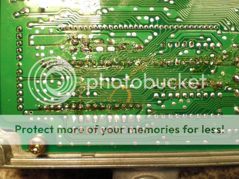
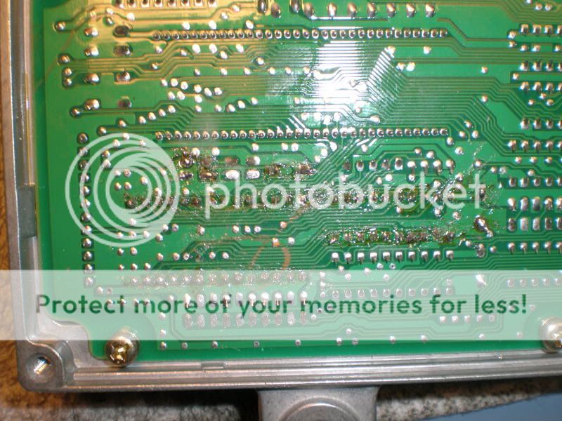
decided to chip my p28 by myself with hardly any electrical experience but the know-how to use a soldering gun and some common sense. soldered everything in and now i cant get my car to start (luckily i have a spare ecu) does anyone know whats wrong with it? it starts fine with my other ecu. does the rom need to be soldered into the socket? ill upload some pictures.


 01-04-2008, 04:46 PM
#2
First off, what kind of capacitors do you have in c51, c52? http://www.phearable.net/image...s.gif , look at this picture, and make sure your stuff lines up and matches what they used. I think the problem is the capacitors first off. Secondly, im not bashin on your soldering skills, but they done look like they're getting a great connection. I just chipped mine, im putting my car back together tomarrow so i guess ill be able to see how good i did. *edit* i dont know if this will help, but when i solder i put the tip of the iron right at the pin im soldering and just touch the solder to it and let it fill in the hole. Also, i've heard its recommended from chipping sites that after you de-solder to rub those sections of the board with a type of alcohol to remove the factory protective coating off the board for a good connection.
01-04-2008, 06:01 PM
#3
Junior Member
Join Date: Aug 2007
Location: Funky 600block Norcal
Posts: 592
Likes: 0
Received 0 Likes
on
0 Posts
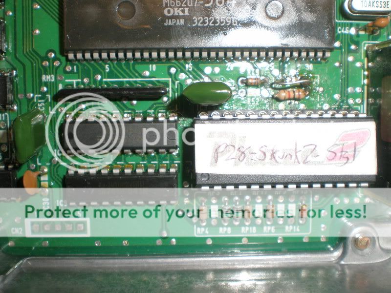
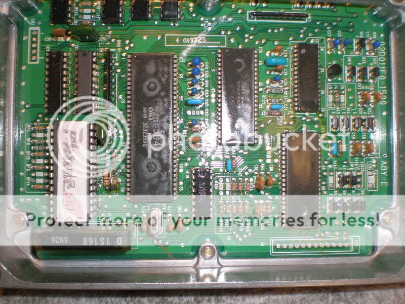
You soldered the 74hc chip in the wrong direction the little half moon shape has to be facing the front of the ecu. Those capacitors also don't look right. Try cutting the jumper on j1 and then starting the car. It was late and I wasn't paying attention and I popped my chip in like that facing the wrong direction my car started but had a solid cel unjumped it and it still had a solid cel pulled out the 74hc chip and the cel is off. I don't know if its too late now the ecu might be messed up. You should always use a socket when chipping ecus, that way you just pull up on the chip rather then desoldering it. Where did you get your chip from anyway?
01-04-2008, 06:05 PM
#4
Honda-Tech Member
Thread Starter
Join Date: Nov 2005
Location: laguna niguel, ca, usa
Posts: 1,600
Likes: 0
Received 0 Likes
on
0 Posts
<TABLE WIDTH="90%" CELLSPACING=0 CELLPADDING=0 ALIGN=CENTER><TR><TD>Quote, originally posted by z6hatchboy »</TD></TR><TR><TD CLASS="quote">First off, what kind of capacitors do you have in c51, c52? http://www.phearable.net/image...s.gif , look at this picture, and make sure your stuff lines up and matches what they used. I think the problem is the capacitors first off. Secondly, im not bashin on your soldering skills, but they done look like they're getting a great connection. I just chipped mine, im putting my car back together tomarrow so i guess ill be able to see how good i did. *edit* i dont know if this will help, but when i solder i put the tip of the iron right at the pin im soldering and just touch the solder to it and let it fill in the hole. Also, i've heard its recommended from chipping sites that after you de-solder to rub those sections of the board with a type of alcohol to remove the factory protective coating off the board for a good connection.</TD></TR></TABLE>
hmmm a little late for the rubbing alcohol thing as i have already desoldered it and re-soldered it haha. really? the capicitor is wrong? its a .01uf blah blah capacitor with polyester film, radio shack didnt have any of those nifty tan ones... would that matter? haha and i know i suck at soldering haha.
hmmm a little late for the rubbing alcohol thing as i have already desoldered it and re-soldered it haha. really? the capicitor is wrong? its a .01uf blah blah capacitor with polyester film, radio shack didnt have any of those nifty tan ones... would that matter? haha and i know i suck at soldering haha.
01-04-2008, 06:05 PM
#5
<TABLE WIDTH="90%" CELLSPACING=0 CELLPADDING=0 ALIGN=CENTER><TR><TD>Quote, originally posted by ejoner »</TD></TR><TR><TD CLASS="quote">You soldered the 74hc chip in the wrong direction the little half moon shape has to be facing the front of the ecu. Those capacitors also don't look right. Try cutting the jumper on j1 and then starting the car. It was late and I wasn't paying attention and I popped my chip in like that facing the wrong direction my car started but had a solid cel unjumped it and it still had a solid cel pulled out the 74hc chip and the cel is off. I don't know if its too late now the ecu might be messed up. You should always use a socket when chipping ecus, that way you just pull up on the chip rather then desoldering it. Where did you get your chip from anyway?
</TD></TR></TABLE>
Good call on the 74hc i missed that, when you solder anything with lettering/numbering make sure its orientation matches the rest. I noticed you mentioned use a socket, you dont need one for the small 74hc, but it looks like he used one with program chip.
</TD></TR></TABLE>
Good call on the 74hc i missed that, when you solder anything with lettering/numbering make sure its orientation matches the rest. I noticed you mentioned use a socket, you dont need one for the small 74hc, but it looks like he used one with program chip.
01-04-2008, 06:07 PM
#6
Honda-Tech Member
Thread Starter
Join Date: Nov 2005
Location: laguna niguel, ca, usa
Posts: 1,600
Likes: 0
Received 0 Likes
on
0 Posts
<TABLE WIDTH="90%" CELLSPACING=0 CELLPADDING=0 ALIGN=CENTER><TR><TD>Quote, originally posted by ejoner »</TD></TR><TR><TD CLASS="quote">You soldered the 74hc chip in the wrong direction the little half moon shape has to be facing the front of the ecu. Those capacitors also don't look right. Try cutting the jumper on j1 and then starting the car. It was late and I wasn't paying attention and I popped my chip in like that facing the wrong direction my car started but had a solid cel unjumped it and it still had a solid cel pulled out the 74hc chip and the cel is off. I don't know if its too late now the ecu might be messed up. You should always use a socket when chipping ecus, that way you just pull up on the chip rather then desoldering it. Where did you get your chip from anyway?
</TD></TR></TABLE>
my chip does have a socket, i bought it off ebay, that was the only place i could find one that was right for my car (d16 w/vtec@4800rpms)
</TD></TR></TABLE>
my chip does have a socket, i bought it off ebay, that was the only place i could find one that was right for my car (d16 w/vtec@4800rpms)
01-04-2008, 06:08 PM
#7
If they're the same ohm i dont see why it wouldnt work, but i dont know if it would matter, i just know thats what everyone uses. I didnt use alcohol on mine either, lol.
Trending Topics
01-04-2008, 06:09 PM
#8
Honda-Tech Member
Thread Starter
Join Date: Nov 2005
Location: laguna niguel, ca, usa
Posts: 1,600
Likes: 0
Received 0 Likes
on
0 Posts
<TABLE WIDTH="90%" CELLSPACING=0 CELLPADDING=0 ALIGN=CENTER><TR><TD>Quote, originally posted by z6hatchboy »</TD></TR><TR><TD CLASS="quote">
Good call on the 74hc i missed that, when you solder anything with lettering/numbering make sure its orientation matches the rest. I noticed you mentioned use a socket, you dont need one for the small 74hc, but it looks like he used one with program chip.</TD></TR></TABLE>
should the chip be soldered into the socket?
01-04-2008, 06:11 PM
#9
On the little one, i dont think so, everyone does it like you did, right on the board. On the big one with the board though, i doubt it either, b/c thats the purpose of the socket to make it interchangable so your good, might want to work on those connections though 
01-04-2008, 06:14 PM
#10
Honda-Tech Member
Thread Starter
Join Date: Nov 2005
Location: laguna niguel, ca, usa
Posts: 1,600
Likes: 0
Received 0 Likes
on
0 Posts
im about to go flip the 74 chip what do u mean fix my connections? which ones should be fixed? And should i cut that jumper? or see if it works and if not then cut it?
01-04-2008, 06:19 PM
#11
Im just reffering to some of those solder's just add some more to it. The jumper is a switch basically, when connected the car runs off the chip when cut or disconnected the car runs off of its stock componets (the way it was before chipped). You can cut it and see if the car will run that way.
01-04-2008, 07:06 PM
#12
Honda-Tech Member
Thread Starter
Join Date: Nov 2005
Location: laguna niguel, ca, usa
Posts: 1,600
Likes: 0
Received 0 Likes
on
0 Posts
<TABLE WIDTH="90%" CELLSPACING=0 CELLPADDING=0 ALIGN=CENTER><TR><TD>Quote, originally posted by z6hatchboy »</TD></TR><TR><TD CLASS="quote">Im just reffering to some of those solder's just add some more to it. The jumper is a switch basically, when connected the car runs off the chip when cut or disconnected the car runs off of its stock componets (the way it was before chipped). You can cut it and see if the car will run that way.</TD></TR></TABLE>
this de-soldering business is a pain in the *** and i just ran out of copper braided wire. does it matter if its on with the letters upside down?? i also just noticed one of those little wires on the board popped up!! is that bad???
this de-soldering business is a pain in the *** and i just ran out of copper braided wire. does it matter if its on with the letters upside down?? i also just noticed one of those little wires on the board popped up!! is that bad???
01-04-2008, 09:18 PM
#14
Junior Member
Join Date: Aug 2007
Location: Funky 600block Norcal
Posts: 592
Likes: 0
Received 0 Likes
on
0 Posts
Yes if the wire on the board popped up its bad actually I think its irreparable the little notch at the edge of the chip has to be facing the front of the ecu (plugs) You should buy a desoldering iron about 10 bucks at radioshack. Like I said before I don't know if this will fix your problem tho as the ecu can be permanently damaged.
01-04-2008, 09:52 PM
#15
Honda-Tech Member
iTrader: (2)
Join Date: Aug 2003
Location: Killadelphia
Posts: 1,572
Likes: 0
Received 0 Likes
on
0 Posts
Your ECU has most likely been fried and if it hasn't, it will be after you try another go at soldering that chip in.
Time for a new ECU, it's more cost effective to just let someone know what they are doing chip your ****. Seriously, it's like 100$ for a P28, and 150$ for a P28 with ZIF socket.
Time for a new ECU, it's more cost effective to just let someone know what they are doing chip your ****. Seriously, it's like 100$ for a P28, and 150$ for a P28 with ZIF socket.
01-05-2008, 01:53 AM
#16
iTrader: (2)

You installed the 73HC373 backwards.
Your soldering really isn't safe, any of those joints could fail on a hot day.
Hopefully you didn't damage any of the traces on the board. If you can't get the setup to work just remove/cut j1 and drive on the stock ecu until you can find a replacement unit that is chipped/socketed
Your soldering really isn't safe, any of those joints could fail on a hot day.
Hopefully you didn't damage any of the traces on the board. If you can't get the setup to work just remove/cut j1 and drive on the stock ecu until you can find a replacement unit that is chipped/socketed

Thread
Thread Starter
Forum
Replies
Last Post