When you click on links to various merchants on this site and make a purchase, this can result in this site earning a commission. Affiliate programs and affiliations include, but are not limited to, the eBay Partner Network.
The tachometer in my Civic is not accurate - my tachometer reads lower than the actual RPM throughout the entire range, and the discrepancy gets worse as RPMs increase. I know mine is reading incorrectly because I have Hondata which displays the actual RPM of the engine, but if you've ever taken your stock Civic up to redline, you may have noticed that the tachometer shows a different redline than what you expected. The issue is that the tachometer has electrolytic capacitors on its board, and just like the ones in the ECU (and ICU), they have a limited life and will go bad over time. My Civic is a 1994, so the capacitors are 25 years old. With capacitors this old, the best case is that your tachometer is just inaccurate and the worst case is that the capacitors begin leaking their electrolyte which can damage the board. This post will walk you through replacing the electrolytic capacitors on your tachometer and then calibrating it so that your tachometer is once again accurate.
Below is a very helpful YouTube video which shows how to test and adjust the tachometer on the bench. Like the one in the video, my tachometer was not going to be fixed simply by adjusting the potentiometer. Unfortunately, I don't have an oscilloscope or an Arduino board to generate the signal with. I did however find
Remove the tachometer from the car
Use a plastic pry tool to pry out the hazard switch and disconnect the connector to remove the switch. Use a #2 Phillips screwdriver to remove the one screw behind the hazard switch and two screws over the gauge cluster, then carefully pry the bezel out of the dash with plastic pry tools. Disconnect the connector for the clock, then remove the bezel. Use a #2 Phillips screwdriver to remove the four screws holding the gauge cluster into the dash then disconnect the four electrical connectors from the back of the cluster and remove it from the dash. Pull the rubber tip off of the trip odometer reset button, then carefully release the 6 clips around the outside of the gauge cluster (3 on top, 3 on bottom) to remove the front half of the cluster. Use a #2 Phillips screwdriver to remove the three silver screws from the back of the cluster that hold the tachometer in, and remove the tachometer.
Disassemble the tachometer
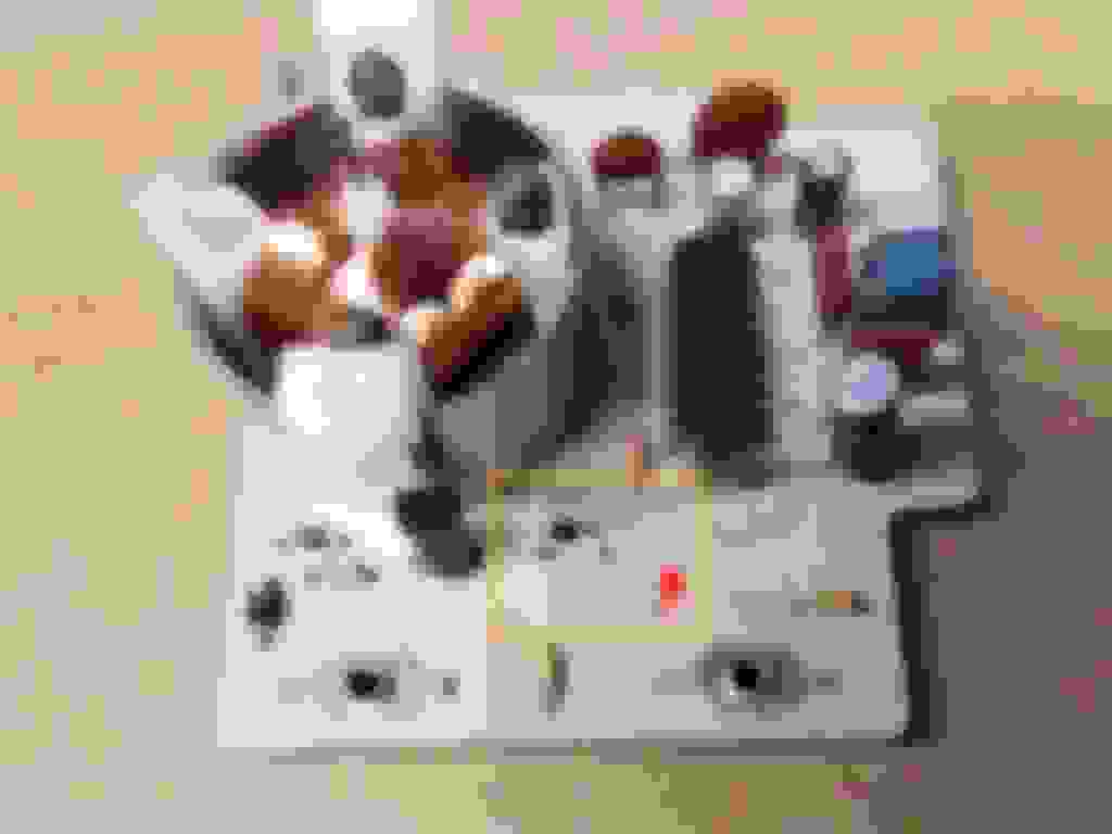
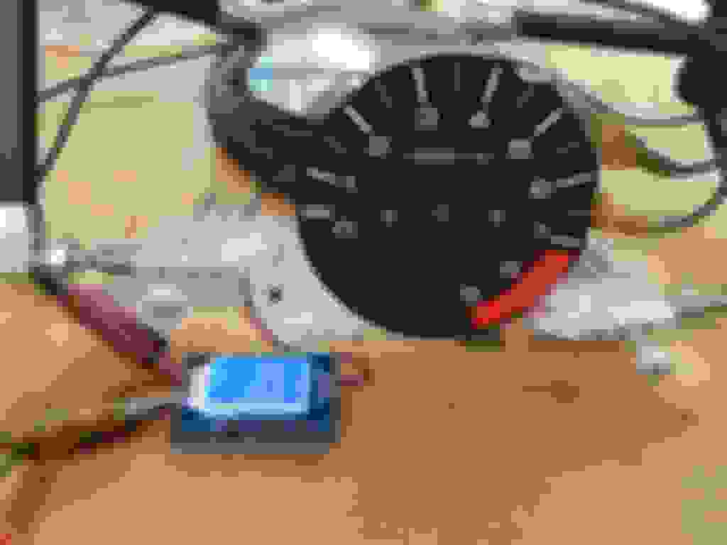
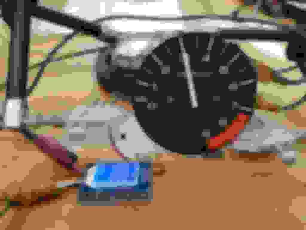
Use a plastic pry tool to remove the indicator (needle) from the tachometer. Use a #1 Phillips screwdriver to remove the two screws holding the dial face to the tachometer, then remove the dial face. The picture below shows what the fully disassembled tachometer looks like and where the relevant components are located.
Replace the capacitors
Please note that when working with capacitors, you risk being shocked if the capacitors are charged and you are not careful. This can happen even after the power has been removed for a significant period of time. If you’re doing this repair, it’s assumed that you know your way around electronics.
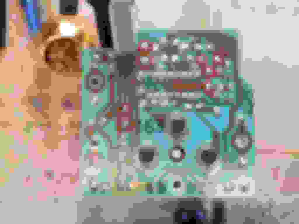
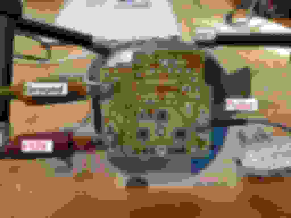
There are four electrolytic capacitors on the tachometer board. I didn’t bother testing which one was bad, and instead just replaced all four. These capacitors are marked as C1 (2200 uF / 16V), C2 (3.3 uF / 50V), C4 (2.2 uF / 50V), and C6 (0.47 uF / 50V). I tried matching the diameter and height of my replacement capacitors to be the same as the originals, but I couldn’t order C6 from DigiKey in the same size unless I ordered a bulk quantity.
Use a soldering iron and desoldering pump to remove the old capacitors. I like to use a sharpie to mark which pads to desolder on the back of the board so I don’t accidentally desolder the wrong component. Solder the new capacitors into the correct position and trim the leads. A little bit of flux on the pads helps the solder wet out nicely.
These electrolytic capacitors are polar, meaning they have a positive and negative lead. The negative lead on polar electrolytic capacitors is typically shorter than the positive lead, and the negative lead will usually be aligned with a stripe on the canister. The tachometer board has a “+” symbol printed on it (as well as a mark indicating which direction the stripe should face) by each electrolytic capacitor to show the polarity as well. See the picture below. Do not solder your capacitors in backwards.
Assemble the signal generator
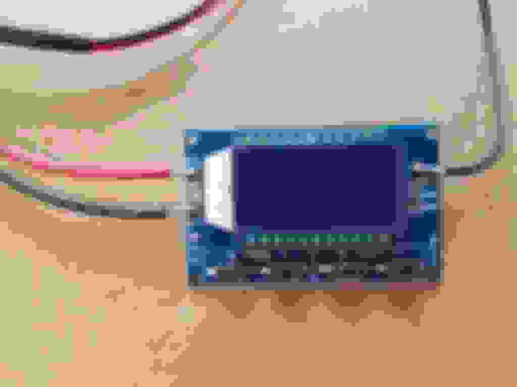
Solder a red wire to 'Vin+' and a black wire to 'Vin-' on the signal generator – these will be used to connect it to a battery for power into the signal generator. Solder a third wire to ‘PWM’ on the signal generator (it’s a purple wire in my pictures), then crimp a ring terminal to the other end of this wire. You’re also going to need a way to provide +12V and a ground to the tachometer.
Reassemble the tachometer and connect the signal generator
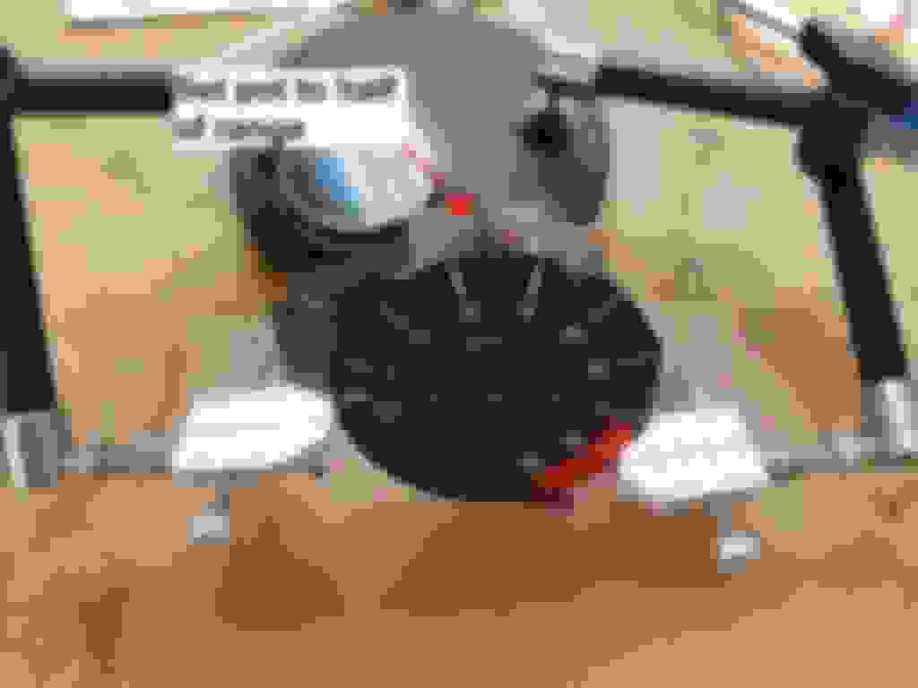
Use a #1 Phillips screwdriver to reattach the dial face to the tachometer. Do not install the indicator yet. Use a small flat head screwdriver to set the potentiometer on the tachometer about halfway through its range. Attach the wire coming from PWM on the signal generator to the TA input on the tachometer using the screw. Connect the Vin+ and Vin- wires from the signal generator to a 12V battery. Connect the IGN screw on the tachometer to +12V, and connect GND from the tachometer to the battery ground.
Calibrate tachometer
The signal generator I’m using allows you to adjust frequency (Hz) and duty cycle (%). Set duty cycle at 50%. The conversion from Hz to RPM is 1 Hz = 30 RPM (if you want to see the math to get there, go watch the YouTube video mentioned above). Therefore 100 Hz on the signal generator should produce a reading of 3,000 RPM on the tachometer, and 250 Hz should produce a reading of 7,500 RPM.
With all the wires connected to the signal generator and tachometer, set the signal generator to produce a frequency of 100 Hz. Now, carefully reinstall the indicator onto the tachometer, aligning the pointer at 3,000 RPM. Do not push the indicator all the way on yet, in case you need to reposition it. Temporarily disconnect the power to the signal generator and/or tachometer – you want the indicator to return to zero. Reconnect power and at 100 Hz, the indicator should return to 3,000 RPM. If needed, small adjustments can be made using the potentiometer. Now, set the signal generator to produce a frequency of 250 Hz. The indicator should now be pointing at 7,500 RPM. Again, use the potentiometer to make fine adjustments if needed. If everything checks out, press the indicator the rest of the way onto the shaft and re-check the reading. If the potentiometer won’t bring the indicator into the range it should be, carefully remove and reposition the indicator.
Disconnect the signal generator and power wires for the tachometer.
Reinstall
Installation is the reverse of disassembly. Reinstall the tachometer into the gauge cluster, reinstall the cluster into the car, and reinstall the bezel. Congrats, you’ve just fixed your tachometer.
Thanks guys. You should give it a shot @JRCivic1 - it wasn't too bad. If you don't feel up to it though, wrap a couple of $20's around each one and send 'em!
this is something i could have used a long time ago, but i will be replacing my cluster soon and this might just come in handy, appreciate the post and info
I follow the instruction, replace all capacitor and recalibrate it. But unfortunately 2 months later my tachometer goes wrong one more time. I suppose potentiometer can goes wrong, what do you think ?
I just read through this again because it's such a good thorough write-up. It should be stickied again at the top of the stcikies as an example of how all write-ups need to be done!
Thanks guys. You should give it a shot @JRCivic1 - it wasn't too bad. If you don't feel up to it though, wrap a couple of $20's around each one and send 'em!
For reals?
Can I send you the entire cluster for speedo and tacho service?
My 1994 Civic sedan varies between around 2500rpm or 3500rpm at an indicated 80mph in fifth gear. My 1994 Civic coupe fuel cutoff is around an indicated 6000rpm even though the redline is around 7200rpm. Sedan has around 173k miles and coupe has 495k miles. This write up makes it less daunting to a novice like me.
Thanks for the kinds words guys. A few folks have asked if they can send me their tachometers for repair. My intention with this write-up was to instill the confidence to do it yourself! If you just don't feel confident though, you can message me and depending on my amount of free time and desire, I may be able to help you out.
Regarding the speedometers, I have not tried repairing one of those, but I'm fairly certain it would be a similar process - just use the correct replacement capacitors. I believe the speedometer has two 1000 uF 16V capacitors. I have this thread bookmarked for speedometer to VSS correlation - it was done using an Accord, so I haven't verified this works on the Civic, but I would imagine it's the same.
I can confirm the QTY 2 x 16v, 1000 uF capacitors for the speedo:
Thanks for the thread, I was able to recalibrate my tach after replacing caps and losing the needle setting.
I did go through a lot of headaches before I finally got it though. I had torn down the whole gauge cluster, including the three dark screws holding the "can" on the back of the tach. I DON'T recommend anyone do this, because I ended up with cracked plastic around the posts, so that when I went to re-tighten the screws, one of them just kept spinning.
After replacing caps, and putting it back together I was scratching my head, cause the tach was acting really weird all over the place, like the needle went lower as I increase frequency, etc. Basically tried three different pulse generators thinking something about the signal was not right. I finally realized that the spinning of the post had torn one of the thin galvo wires off so that coil wasn't getting activated. Luckily I was able to patch it up with a spare cutoff component lead. Anyways, just figured I'd mention that in case anyone else does something stupid like me.
...
But my other reason for posting in this thread is that I also took the speedo apart and not sure the best way to set that needle back to "normal".
I know there's no trim pots to adjust, so I guess it just has to be placed at some reasonably correct position. But it seems like it doesn't respond 100% linearly to pulse signals. Like if I send signal for 70mph, and put the needle right on 70, then when I send half that frequency its reading like 40 instead of 35. Or if I set needle based on 35mph then it reads too low at highway speeds.
I don't think its another issue of torn wire, but maybe my calculation of scaling is wrong somehow? Or maybe speedo doesn't like 50% duty cycle? Does anyone have an image capture of speed signal waveform?
Here is me "showing my work" for the calculations:
Now some conversion constants to show how the units cancel in the final equation:
3600 seconds / hour
63360 inches / mile
4 Hz*s / rev this is a little odd of a unit so some further explanation:
4 pulse / tire revolution (based on a comment above) is that right?
1 pulse / s = 1 Hz multiply both sides by 1 second means that we can substitute (pulse) with (Hz*s)
Multiply D * Pi to get trie circumference aka inches per revolution, and then apply the other constants:
D * Pi (in / rev) * 3600 (s / hr)
------------------------------------------ = X (mph/Hz)
4 (Hz * s / rev) * 63360 (in / mi)
inches cancel, seconds cancel, revs cancel, and you end up with (mph / Hz)
So you should be able to multiply frequency in Hz by that resulting value to get mph:
Freq(Hz) * X(mph/Hz) = mph
For my tires i got X = 1.01477 mph / Hz
Did I go wrong anywhere?
Lastly, I think some cars do this but I can't remember the stock behavior: should the needle just be set to barely jump off the peg when ignition is on, or does it stay pegged at 0 (the whole scaling at the very bottom is kinda wonky anyways) ? Would that possibly be a simpler/better way to set it?

 04-26-2019, 02:25 PM