

DIY Engine block Blueprinting techniques


Thread Starter
moderator emeritus
Joined: Oct 2002
Posts: 16,357
Likes: 6
From: Cantonment, FL
This is not a topic regarding your typical low budget engine assembler simply using plastigauge, a torque wrench, and a set of feeler gauges. I know not everyone can afford to do these processes (or think they are necessary) completely and its understandable and not every dimension "has" to be checked with as much concerned when doing a stock rebuild but when racing engines are in question, it definitely requires a different approach. I'm hoping this will open the mind of the people who read it and didnt know such practices even existed. I'm not going to be able to cover everything as I dont know everything and this is more of a "leading" topic to get people involved.
This is going to be an in depth discussion on the proper ways to BUILD an engine. Anyone can put an engine together and call it "built". Well did you build it or just assemble it trusting the manufacturers, your buddies or any other reason why you wouldnt check the tolerances and clearances closely after spending 5-10k dollars in engine parts?
After the demise of my engine and being built by someone I thought would have put a little more concern towards the clearances of a racing engine (R.I.P. Don Flores) and knowing I was going to be clearancing this engine myself, the right way, it has led me to dig pretty deep into reading tech articles which has still left me with a few questions which I will talk about soon below.
To blueprint an engine in the common way you need a standard set of tools to do this and this is what I have and its getting bigger:
These are the tools I have to build engines:
Matco 1/2" torque wrench (25-250lbs)
Craftsman 3/8" torque wrench (0-75lbs)
Fowler digital bore gauge
1-2" Mitutoyo Mic
2-3" Mitutoyo Mic
3-4" Matco (Fowler) Mic
0-1" digital rounded anvils by mitutoyo (reads to .00005 and is used for bearing thickness)
Mitutoyo Mic stand helps keep the measurements consistent as the holding the mic will increase its temp and fudge the reading a tad
Mitutoyo vernier caliper
Matco Feeler gauge set
a few dial indicators with a magnetic stand
Mitutoyo Depth gauge
Make sure your bore gauge and mics have a resolution to .0001 minimum.
So with that said, you have a basic set of tools needed to begin with the basic blueprinting procedure.
So how do you read a micrometer?
First of all you want to make sure that your Mic is calibrated and it is reading a true 0. Calibration gauges usually come with the micrometer you buy but if not, you can buy them in sets. I wont get into calibration but know that its important that you are reading the right measurement.
Take your micrometer and whatever you are measuring and move the dial until the two ends of the mic are snug with the object.

I chose to use a yuengling bottle i just finished.
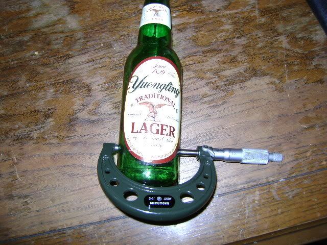
Now is the tricky part. The more you hold the mic, the hotter it is going to get and the more screwed your readings are going to get. So be as fast and as accurate as possible. Typically, in our situations, the part we are measuring will be round so you cant exactly have two flat pieces of the mic sit flat with a round surface. Key here is to make sure that the middle of the flat pieces (anvil and spindle) are sitting on the round object on both sides. You will have achieved this if you have an even gap all the way around the anvil and spindle end piece and the round thing you are measuring.
You want to be able to slide the mic off without force, but not so easily to where the mic is sloppy. It needs to be snug. Lock the mic and pull it off.
Now how do you read what you got?
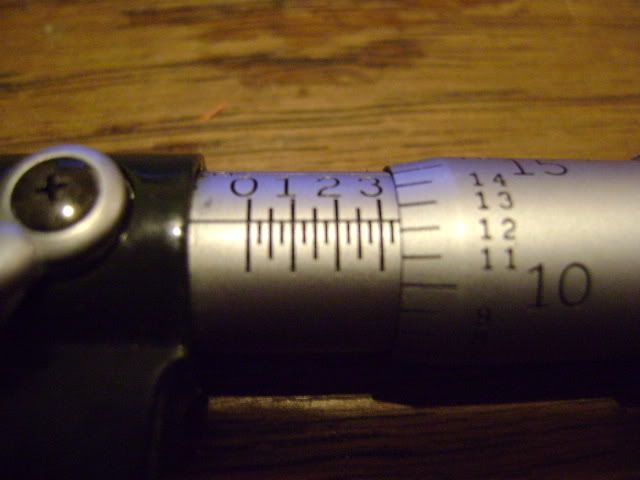

This is a 2-3" mic so all your readings will be from 2.0001 to 3.0001
The horizontal "ruler" (sleeve) is X. 2.X001. Each dash mark represent .25.
The numbers on the thimble (the thing that spins) are 2.0XX1.
As you can see, the line on the sleeve is between 12 and 13 and the thimble is lined up beyond the 3. So as of right now, our number is 2.3XXX. Each small line is .25 so add .25 and .12 and you get .37 and the next two numbers in the measurement, 2.337X
For the last number in the measurement, look at the last picture. You want to find the line that matches best with the other and that will be your last number. in this case it is 5 and gives us a final measurement of the yuengling bottle of 2.3375"
beer ftw
So we now know how to read a micrometer. Progress!
So what procedure is next? Lets talk about measuring your pistons/cylinder bore/rings.
That standard procedure, in my opinion, is to measure your piston and right down each measurement for each piston about midway down the skirt. This is where most of the thrust wear will occur and is where you want to set your clearance. So now you need to measure your cylinder bore as well as the taper and out of round (X and Y axis). In order to do this and be accurate, I have found it quickest to dial in your bore gauge using a micrometer set at a constant size. This is achieved by using the different extensions on the bore gauge. Once you have the bore gauge set to the constant, zero out the bore gauge. You can then set the bore gauge in the cylinder on the X axis measuring at near the top, middle and near bottom of the bore rocking the gauge back and forth to find the smallest measurement at each 3 points. This will give you the bore taper. Measure the Y axis at the same points and that will give you the bore out of round measurement.
Cool, we have numbers. What do we do with them?
So with these measurements known. How much out of round is too much? or how much taper is too much? I mean the rings are pretty damn thin. Is it the rings fault that you have blow by in your fresh motor or is it something else?
I am subscribed to an engine building magazine which has gone into great depth regarding this topic as well as its effect on piston wear, ring sealing and the different uses of various ring materials and thicknesses.
A tech article in this magazine said in most instances, a ring failure typically is not the rings, rather, more commonly is poor bore geometry (the taper and out of round) as well as the hone (surface smoothness, crosshatch...etc). So if you are a garage builder and have to rely on a machine shop to know what they are doing, how is it possible to double check their work and know what is right and what is wrong? What extra step can you take to ensure the crosshatch is at the proper degree? that the surface finish is as smooth as it needs to be? Any tools tricks to figure that out?
We already know how to check a machine shops work for out of round and taper which are going to be a huge factor in ring seal! Blow by is a loss in compression which is a loss in power. We cant have that!
Sorry, got off track!
Anyway, so you have your pistons measured and your cylinders measured. Are you happy with the clearance? Did you take into consideration that a forged piston will have a larger expansion rate than a cast piston?
99% of the time, you are going to have to send the block to the machine shop so they can bore/hone the cylinder to meet the clearance specification that you are looking for. Remember than an increase in HP is increased heat and RPM is another large factor. How similar would a PTW clearance be of a 1000whp/6000rpm turbo engine vs a 300whp/10000rpm Naturally aspirated engine? How much PTW is too much for a given operating condition? Endurance racing? Drag racing? There is a HUGE difference!!!!!
How about the weight of the piston in relation to the crank (bob weight)? The long rod, short rod discussion. Its all part of the blueprinting procedure so how do you decide one over another and why?
Lets go deeper into the engine block with the crank/crank bores/bearings.
You are going to use the same technique with the crank as you did the with pistons and cylinder walls except you are going to be determining what bearing thickness you are going to use to jam between the crank and crank bore.
Ill link you to his post for an informative tech article by Earl Laskey (R.I.P.)
https://honda-tech.com/forums/all-motor-naturally-aspirated-44/honda-bearing-color-thickness-chart-everyone-who-loves-using-oem-bearings-715490/
So there you have the HONDA bearing thicknesses spelled out to you. They are the same for B, D, H, F....not sure about K but id imagine its the same as far as thickness goes however, H and F series do not have a RED bearing...which sucks LOL
You now have all your clearances for the crank bores as well as the crank journals along the vertical axis (measuring the vertical axis, 180 for the bearing parting line, is the standard practice as it is the thickest part of the bearing and bearings tend to taper thinner towards the parting line).
What else do we really need to know? How about crank bore alignment? Crank straightness? Crank journal roundness? ALL very important. If you have a bearing clearance of .0020 but the crank journal is .0005 out of round and you didnt measure it......well your measurement now might as well have been .0015. Might not seem all that much but at 10000rpm, those little voids could cause havok.
Another idea to keep in mind is journal/rod/crank distortion, especially when the piston is changing directions! When this happens, the rod clearance shrinks horizontally due to rod stretch. Rod stretch......keep that in mind when determining Piston to Valve and Piston to Head. An aluminum rod can grow as large as .030" at the top RPM. Talk about a linear compression increase LOL!
We've got this mind set now that things might not be so cookie cutter when putting an engine together and there is A LOT that can go wrong. What else do we need to consider? Oh yes, crank straightness and crank bore alignment. What good is a crank bearing clearance when either the crank isnt straight or #1 main bore centerline sits .0005" off from the rest or any other combination of it. How is that going to effect your dynamics clearances (engine in motion)?
I would like to know how you guys are properly measuring crank straightness and how, without expensive equipment, you are measuring crank bore alignment? Those are the main questions I was getting to but I figured I would try and make a discussion about it all!
Thanks for reading and this is an open discussion!!!!! Sorry if I skipped over a few things, my fingers are getting tired.
This is going to be an in depth discussion on the proper ways to BUILD an engine. Anyone can put an engine together and call it "built". Well did you build it or just assemble it trusting the manufacturers, your buddies or any other reason why you wouldnt check the tolerances and clearances closely after spending 5-10k dollars in engine parts?
After the demise of my engine and being built by someone I thought would have put a little more concern towards the clearances of a racing engine (R.I.P. Don Flores) and knowing I was going to be clearancing this engine myself, the right way, it has led me to dig pretty deep into reading tech articles which has still left me with a few questions which I will talk about soon below.
To blueprint an engine in the common way you need a standard set of tools to do this and this is what I have and its getting bigger:
These are the tools I have to build engines:
Matco 1/2" torque wrench (25-250lbs)
Craftsman 3/8" torque wrench (0-75lbs)
Fowler digital bore gauge
1-2" Mitutoyo Mic
2-3" Mitutoyo Mic
3-4" Matco (Fowler) Mic
0-1" digital rounded anvils by mitutoyo (reads to .00005 and is used for bearing thickness)
Mitutoyo Mic stand helps keep the measurements consistent as the holding the mic will increase its temp and fudge the reading a tad
Mitutoyo vernier caliper
Matco Feeler gauge set
a few dial indicators with a magnetic stand
Mitutoyo Depth gauge
Make sure your bore gauge and mics have a resolution to .0001 minimum.
So with that said, you have a basic set of tools needed to begin with the basic blueprinting procedure.
So how do you read a micrometer?
First of all you want to make sure that your Mic is calibrated and it is reading a true 0. Calibration gauges usually come with the micrometer you buy but if not, you can buy them in sets. I wont get into calibration but know that its important that you are reading the right measurement.
Take your micrometer and whatever you are measuring and move the dial until the two ends of the mic are snug with the object.
I chose to use a yuengling bottle i just finished.
Now is the tricky part. The more you hold the mic, the hotter it is going to get and the more screwed your readings are going to get. So be as fast and as accurate as possible. Typically, in our situations, the part we are measuring will be round so you cant exactly have two flat pieces of the mic sit flat with a round surface. Key here is to make sure that the middle of the flat pieces (anvil and spindle) are sitting on the round object on both sides. You will have achieved this if you have an even gap all the way around the anvil and spindle end piece and the round thing you are measuring.
You want to be able to slide the mic off without force, but not so easily to where the mic is sloppy. It needs to be snug. Lock the mic and pull it off.
Now how do you read what you got?
This is a 2-3" mic so all your readings will be from 2.0001 to 3.0001
The horizontal "ruler" (sleeve) is X. 2.X001. Each dash mark represent .25.
The numbers on the thimble (the thing that spins) are 2.0XX1.
As you can see, the line on the sleeve is between 12 and 13 and the thimble is lined up beyond the 3. So as of right now, our number is 2.3XXX. Each small line is .25 so add .25 and .12 and you get .37 and the next two numbers in the measurement, 2.337X
For the last number in the measurement, look at the last picture. You want to find the line that matches best with the other and that will be your last number. in this case it is 5 and gives us a final measurement of the yuengling bottle of 2.3375"
beer ftw
So we now know how to read a micrometer. Progress!
So what procedure is next? Lets talk about measuring your pistons/cylinder bore/rings.
That standard procedure, in my opinion, is to measure your piston and right down each measurement for each piston about midway down the skirt. This is where most of the thrust wear will occur and is where you want to set your clearance. So now you need to measure your cylinder bore as well as the taper and out of round (X and Y axis). In order to do this and be accurate, I have found it quickest to dial in your bore gauge using a micrometer set at a constant size. This is achieved by using the different extensions on the bore gauge. Once you have the bore gauge set to the constant, zero out the bore gauge. You can then set the bore gauge in the cylinder on the X axis measuring at near the top, middle and near bottom of the bore rocking the gauge back and forth to find the smallest measurement at each 3 points. This will give you the bore taper. Measure the Y axis at the same points and that will give you the bore out of round measurement.
Cool, we have numbers. What do we do with them?
So with these measurements known. How much out of round is too much? or how much taper is too much? I mean the rings are pretty damn thin. Is it the rings fault that you have blow by in your fresh motor or is it something else?
I am subscribed to an engine building magazine which has gone into great depth regarding this topic as well as its effect on piston wear, ring sealing and the different uses of various ring materials and thicknesses.
A tech article in this magazine said in most instances, a ring failure typically is not the rings, rather, more commonly is poor bore geometry (the taper and out of round) as well as the hone (surface smoothness, crosshatch...etc). So if you are a garage builder and have to rely on a machine shop to know what they are doing, how is it possible to double check their work and know what is right and what is wrong? What extra step can you take to ensure the crosshatch is at the proper degree? that the surface finish is as smooth as it needs to be? Any tools tricks to figure that out?
We already know how to check a machine shops work for out of round and taper which are going to be a huge factor in ring seal! Blow by is a loss in compression which is a loss in power. We cant have that!
Sorry, got off track!
Anyway, so you have your pistons measured and your cylinders measured. Are you happy with the clearance? Did you take into consideration that a forged piston will have a larger expansion rate than a cast piston?
99% of the time, you are going to have to send the block to the machine shop so they can bore/hone the cylinder to meet the clearance specification that you are looking for. Remember than an increase in HP is increased heat and RPM is another large factor. How similar would a PTW clearance be of a 1000whp/6000rpm turbo engine vs a 300whp/10000rpm Naturally aspirated engine? How much PTW is too much for a given operating condition? Endurance racing? Drag racing? There is a HUGE difference!!!!!
How about the weight of the piston in relation to the crank (bob weight)? The long rod, short rod discussion. Its all part of the blueprinting procedure so how do you decide one over another and why?
Lets go deeper into the engine block with the crank/crank bores/bearings.
You are going to use the same technique with the crank as you did the with pistons and cylinder walls except you are going to be determining what bearing thickness you are going to use to jam between the crank and crank bore.
Ill link you to his post for an informative tech article by Earl Laskey (R.I.P.)
https://honda-tech.com/forums/all-motor-naturally-aspirated-44/honda-bearing-color-thickness-chart-everyone-who-loves-using-oem-bearings-715490/
So there you have the HONDA bearing thicknesses spelled out to you. They are the same for B, D, H, F....not sure about K but id imagine its the same as far as thickness goes however, H and F series do not have a RED bearing...which sucks LOL
You now have all your clearances for the crank bores as well as the crank journals along the vertical axis (measuring the vertical axis, 180 for the bearing parting line, is the standard practice as it is the thickest part of the bearing and bearings tend to taper thinner towards the parting line).
What else do we really need to know? How about crank bore alignment? Crank straightness? Crank journal roundness? ALL very important. If you have a bearing clearance of .0020 but the crank journal is .0005 out of round and you didnt measure it......well your measurement now might as well have been .0015. Might not seem all that much but at 10000rpm, those little voids could cause havok.
Another idea to keep in mind is journal/rod/crank distortion, especially when the piston is changing directions! When this happens, the rod clearance shrinks horizontally due to rod stretch. Rod stretch......keep that in mind when determining Piston to Valve and Piston to Head. An aluminum rod can grow as large as .030" at the top RPM. Talk about a linear compression increase LOL!
We've got this mind set now that things might not be so cookie cutter when putting an engine together and there is A LOT that can go wrong. What else do we need to consider? Oh yes, crank straightness and crank bore alignment. What good is a crank bearing clearance when either the crank isnt straight or #1 main bore centerline sits .0005" off from the rest or any other combination of it. How is that going to effect your dynamics clearances (engine in motion)?
I would like to know how you guys are properly measuring crank straightness and how, without expensive equipment, you are measuring crank bore alignment? Those are the main questions I was getting to but I figured I would try and make a discussion about it all!
Thanks for reading and this is an open discussion!!!!! Sorry if I skipped over a few things, my fingers are getting tired.
Honda-Tech Member
Joined: Oct 2005
Posts: 756
Likes: 0
From: Boston, Ma, USA
After you read the above post this video will help you visualize some of the tools Blake is referring to. All credit goes to the owner of the videos, Jafro!
Blueprint 101
Blueprint 101
Honda-Tech Member
Joined: Oct 2005
Posts: 756
Likes: 0
From: Boston, Ma, USA
These videos will help you better understand what Blake is referring to when he explains bearing clearances. Again please read Blake's post FIRST!
Connecting Rods
Crankshaft
Main Bearing Oil Clearance
Connecting Rods
Honda-Tech Member

Joined: Nov 2003
Posts: 1,743
Likes: 1
From: SE, PA, usa
Good write up Blake. You can check the crank bore straightness in the block with a long straight edge. You can also use it to check the deck and head flatness. A good tool to have.
Thread Starter
moderator emeritus
Joined: Oct 2002
Posts: 16,357
Likes: 6
From: Cantonment, FL

Trending Topics
Honda-Tech Member
Joined: Nov 2003
Posts: 1,743
Likes: 1
From: SE, PA, usa
I'm sure there is but I don't know of a more accurate DIY way. Just what I've done in the past. Let's you know if the block is at least close to straight.


my machinist said to plastigauge the clearances anyway when they are fully assembled to double check.
i dont know if its a common practice or not.
he measured it with dial gauge and micrometer and then said i should check plastigauge also in case a bearing is defective in some way or whatever.
i dont know if its a common practice or not.
he measured it with dial gauge and micrometer and then said i should check plastigauge also in case a bearing is defective in some way or whatever.
Honda-Tech Member
Joined: Nov 2004
Posts: 1,117
Likes: 0
From: NY
Thread Starter
moderator emeritus
Joined: Oct 2002
Posts: 16,357
Likes: 6
From: Cantonment, FL
my machinist said to plastigauge the clearances anyway when they are fully assembled to double check.
i dont know if its a common practice or not.
he measured it with dial gauge and micrometer and then said i should check plastigauge also in case a bearing is defective in some way or whatever.
i dont know if its a common practice or not.
he measured it with dial gauge and micrometer and then said i should check plastigauge also in case a bearing is defective in some way or whatever.
however, for the guys that are 100% comfortable with their measurements and their tool use, i dont find it necessary.
So is there anyone else who would like to add anything? I mean I know there are more people who would like more information on these topics!
just asking questions can go a long way!
not sure if you included flywheel and crank pulley im reading on my cell..
but i think they should be included in ballancing also
but i think they should be included in ballancing also

B*a*n*n*e*d
Joined: Dec 2001
Posts: 8,185
Likes: 3
I read what you wrote and I did see all the videos. Definitely great information to give someone a basic overall idea what goes on when building an engine.
There are engine builders and there are engine builders. I remember spending a day with ERL performance and they politely asked me not to take pictures of certain processes. Same with other shops. They need to keep their competitive edge. If these videos or information you posted is not enough that the extra money for professional labor when putting together a honda engine is not worth it, I don't know what is.
I don't want to sound like devil's advocate but if someone pays to get their engine built by a reputable shop or engine builder, they should not take it apart to check clearances. I have seen this many times and its just not a good idea for the obvious reasons. If you are paying to get it done by someone else, you should be able to have enough trust in the process to run it as it comes.
Next, plastigauge vs mics. Yes, you are 100% correct. Plastigauge is not accurate enough.
My opinion on this matter is that performance engines are different than oem type engines. Performance type engines range from blueprinted production enginest to fully prepared race engines.
The issue here that most customers seek improved output without sacrifucing economy, reliability or longetivity. These engines often need to have a good idle, pass emissions etc etc Of course you would expect race engine to produce maximum power and there should be little concern about things such as idle and emissions etc.
For reliability, the saying goes, you have to finish to win. This is a concern when using production components designed to operate within an OEM duty cycle. I read it all the time on the forums and its what most people live by.. OEM this, OEM that.. after all, its a HONDA. Because of these differences, passenger car engines require considerable preparation for racing of high performance use.
Precise engine balancing is crucial for high RPM stability for components like the crankshaft you are asking about.
With bseries it was not as clear due to a lower flowing head than kseries but the issue here is that HONDA has really spoiled us with high performance components camouflaged as street engines.
For example, take a k24a block, install some 12.5 pistons and rods, balance the crank, through a k20a2 head with some cams and boom you have 270 whp
Take a TSX stock engine, throw some cams and e85 and boom, you are almost at the same amount of power with basically a stock engine with bolt ons.
The way these engines respond to cams and other bolt ons, its just unreal. I work with other brand of engines as well and its sad to see when a 3.7L v6 pickups up less HP than a 2 liter honda with the same mods on a 4cylinder.
So what I am trying to say here is that anyone can put together a kseries engine and without any measurements use green bearings all around, follow the HELMS and go from there and see what it makes.
Engine building is just too vast of a subject to be covered in a single thread.
Assembly is a critical stage in engine building. If not properly, the engine will fail. If wrong parts are used, it will fail. The assembler must know correct engine assembly procedures and catch any problems at this stage. Engine could be 99% right and that 1% will come back and get you . I know this first hand.
Prior to actual assembly, subasseblies are required. Cylinder heads must be assembled with careful attention to valve seals, installed heights etc etc Rods and pistons as these videos point out, need to be done right for each cylinder etc.
Skill and knowledge is needed to properly fit most parts in the engine. There is no substitute for clean work habits as the dirt will show up eventually but not immediately.
I just believe that your intentions are very honorable making a thread like this but I hope you understand where I am coming. I can say this because as a manufacturer for camshafts, I do realize that when I post a video of how a cam is made, many people get the idea that its like making hot dogs or something so I often get feedback from honest young people that are misled to believe that anyone can jump in the operator's seat to do what I am doing. So when I speak on this matter, I am speaking for all the people that do this on a daily basis as not as a hobby. It's just a very complicated matter than goes beyond what most people expect out of a honda online all motor forum.
I also have a theory that with forums, only the first few pages matter as far as worthwhile information. Threads beyond pages 2, 3 and 4 for example have little chance of attracting meaninful contribution because by that time, the bird is off to another branch so to speak.
If someone reading this thread wants to become a engine builder I would suggest along with the advice you are giving them as far as tools to consider based on their budget maybe a digital mitutoyo micrometer for what they are going to be measuring often. I paid around $250 for mine because I need to be as precise as I can be.
Along with good equipment, I would expect an apprentice into engine building to know about the following areas/subjects
Correcting alignments between centers
Understanding specifications and tolerances
Comparing units of measurements
Calculation thermal expansion
Making transfer measurements
determining the strength of fasteners
comparing clamping force and torque
identifying threads
removing broken fasteners - (trust me you will have to eventually)
installing helicoils
testing cylinder leakage
testing compression
looking for signs of engine wear
testing manifold vacuum
testing oil pressure
testing cooling systems
disassemble of an engine and what to look for
cleaning engine parts
removing rust and scale
using hand vs power tools, when and when not to
inspecting block components like pistons, rods etc
piston pin clearance and block flatness
reboring and honing and sleeving
weighing pistons and rods
balancing rods
balancing pistons and pins
balancing cranks
balancing flywheels
so much more to write but I think you get the idea.
It's not for everyone and without the right machines, its pointless to invest in precision instrumentation in order to check other people's work when you are going to have to rely on their labor and machines to get the job done since a trip to the machine shop is necessary to perform most of the tasks, might as well find a machine shop that can do the installation as well and save yourself some time and money and trouble.
Become an automotive machinist and engine assembler with require you to
a)go to school for it and work along side a professional
or
b) make a lot of mistakes with the possibility of never learning the right way
It's like how many people learn to play the guitar, through tabs.. they can still play the song and if they are talented enough and have practiced enough, you as the audience will never be able to tell if they can read music or if they are playing by ear... It should not matter I guess if all you care about is their performance during that song.
But when asked to play another song, they might say, sorry I cannot read music.
Same with engine building. It's possible to get played and get fooled because someone has the best tools available and only for example uses SNAP ON and high end stuff in their garage for example.. but if you have enough experience in the scene you will be able to tell if they know what they are talking about by asking them a simple question here and there.
I remember I met a guy with a 30k snapon tool box so naturally I took it for granted he is an expert engine builder, why else would he have invested in such a collection of tools? A few weeks later I was back and I asked him if I could borrow a torque wrench for something I needed that day, his answer.. DON't have one, never got around getting one. lol
Again thank you for making this thread, I just believe that good engine builders are worth every penny and overall are cheap for the amount of knowledge that they bring on the table.
Thread Starter
moderator emeritus
Joined: Oct 2002
Posts: 16,357
Likes: 6
From: Cantonment, FL
There are engine builders and there are engine builders. I remember spending a day with ERL performance and they politely asked me not to take pictures of certain processes. Same with other shops. They need to keep their competitive edge. If these videos or information you posted is not enough that the extra money for professional labor when putting together a honda engine is not worth it, I don't know what is.
I don't want to sound like devil's advocate but if someone pays to get their engine built by a reputable shop or engine builder, they should not take it apart to check clearances. I have seen this many times and its just not a good idea for the obvious reasons. If you are paying to get it done by someone else, you should be able to have enough trust in the process to run it as it comes.
I don't want to sound like devil's advocate but if someone pays to get their engine built by a reputable shop or engine builder, they should not take it apart to check clearances. I have seen this many times and its just not a good idea for the obvious reasons. If you are paying to get it done by someone else, you should be able to have enough trust in the process to run it as it comes.
The problem I have with this last part is my engine, for example. It had maybe 30 passes on it and most of those passes being at a 1/8 mile. I had complete faith in Don but that came to an end once it all went wrong and I torn it apart for inspection. Wrong parts, wrong clearances....just overall bad. And this is what lead me to make this topic. To open some eyes and make people realize what goes into a properly built street/race engine that will have performance along with reliability (given that racing happens....). You get what you pay for right?
Engine building is just too vast of a subject to be covered in a single thread.
Assembly is a critical stage in engine building. If not properly, the engine will fail. If wrong parts are used, it will fail. The assembler must know correct engine assembly procedures and catch any problems at this stage. Engine could be 99% right and that 1% will come back and get you . I know this first hand.
Prior to actual assembly, subasseblies are required. Cylinder heads must be assembled with careful attention to valve seals, installed heights etc etc Rods and pistons as these videos point out, need to be done right for each cylinder etc.
Skill and knowledge is needed to properly fit most parts in the engine. There is no substitute for clean work habits as the dirt will show up eventually but not immediately.
Not to get off topic, but I tuned one of these engines once. I started it up for the first time to set base timing to hear enough piston slap to be concerned immediately about the rest of the engine. When i questioned him, the engine builder told him that if it slaps, it will be due to the silica coating on the pistons. Really now? a coating that is supposed to help with friction and temps is going to cause the pistons to slap....right. Needless to say, it was turbo and didnt last too long. Yet he still trusted his engine builder. ignorance is what I am trying to at least improve in this thread.
If someone reading this thread wants to become a engine builder I would suggest along with the advice you are giving them as far as tools to consider based on their budget maybe a digital mitutoyo micrometer for what they are going to be measuring often. I paid around $250 for mine because I need to be as precise as I can be.
Along with good equipment, I would expect an apprentice into engine building to know about the following areas/subjects
Correcting alignments between centers
Understanding specifications and tolerances
Comparing units of measurements
Calculation thermal expansion
Making transfer measurements
determining the strength of fasteners
comparing clamping force and torque
identifying threads
removing broken fasteners - (trust me you will have to eventually)
installing helicoils
testing cylinder leakage
testing compression
looking for signs of engine wear
testing manifold vacuum
testing oil pressure
testing cooling systems
disassemble of an engine and what to look for
cleaning engine parts
removing rust and scale
using hand vs power tools, when and when not to
inspecting block components like pistons, rods etc
piston pin clearance and block flatness
reboring and honing and sleeving
weighing pistons and rods
balancing rods
balancing pistons and pins
balancing cranks
balancing flywheels
so much more to write but I think you get the idea.
It's not for everyone and without the right machines, its pointless to invest in precision instrumentation in order to check other people's work when you are going to have to rely on their labor and machines to get the job done since a trip to the machine shop is necessary to perform most of the tasks, might as well find a machine shop that can do the installation as well and save yourself some time and money and trouble.
Become an automotive machinist and engine assembler with require you to
a)go to school for it and work along side a professional
or
b) make a lot of mistakes with the possibility of never learning the right way
It's like how many people learn to play the guitar, through tabs.. they can still play the song and if they are talented enough and have practiced enough, you as the audience will never be able to tell if they can read music or if they are playing by ear... It should not matter I guess if all you care about is their performance during that song.
But when asked to play another song, they might say, sorry I cannot read music.
Same with engine building. It's possible to get played and get fooled because someone has the best tools available and only for example uses SNAP ON and high end stuff in their garage for example.. but if you have enough experience in the scene you will be able to tell if they know what they are talking about by asking them a simple question here and there.
I remember I met a guy with a 30k snapon tool box so naturally I took it for granted he is an expert engine builder, why else would he have invested in such a collection of tools? A few weeks later I was back and I asked him if I could borrow a torque wrench for something I needed that day, his answer.. DON't have one, never got around getting one. lol
Again thank you for making this thread, I just believe that good engine builders are worth every penny and overall are cheap for the amount of knowledge that they bring on the table.
I have been working on getting a head start on classes by doing an exceptionally large amount of reading on the history of machining beginning with Gene Haas in the 1980s. It is incredible how technology has changed since then. But then again, what we know now about engines compared to what we did in the 80s is astonishing. I'm excited to have the opportunity to dive deeper.
Honda-Tech Member
Joined: Nov 2003
Posts: 1,743
Likes: 1
From: SE, PA, usa
Most people surfing this forum are just doing this as a hobby. If you are racing seriously/professionally it makes a lot of sense to pay the right person to build your engines for you. Hobbist like myself, build their own engines because they WANT to. I would never pay someone to do it for me because the building and planning part is half the fun! I realize, like most seasoned enthusiasts, that I will not get the same results as a professional engine building program. And that's ok. It's all about learning and improving your own skill set. Having someone do it for me teaches me nothing. I'm sure there are plenty others here that feel the same.
Honda-Tech Member
Joined: Aug 2009
Posts: 7,635
Likes: 3
From: Baton Rouge,Louisiana
Most people surfing this forum are just doing this as a hobby. If you are racing seriously/professionally it makes a lot of sense to pay the right person to build your engines for you. Hobbist like myself, build their own engines because they WANT to. I would never pay someone to do it for me because the building and planning part is half the fun! I realize, like most seasoned enthusiasts, that I will not get the same results as a professional engine building program. And that's ok. It's all about learning and improving your own skill set. Having someone do it for me teaches me nothing. I'm sure there are plenty others here that feel the same.
I do not know if it has been covered because i didn't read it all, and i'm currently at work waiting on a update to finish, but Rod bolt stretch i believe is super overlooked..
Moderator
Joined: Feb 2008
Posts: 3,264
Likes: 2
From: queens, ny
this is a very good write up that everyone is posting here. this will help with basic building of engines and might give some the idea of maybe building there own engine and saving money.
the one question is about the mic. why would the mic get hotter due to being touched several times. if this is happening that might be something defective in the product you use. we have ours calibrated and have our hands all over them. plus the fact you have the specific measurement block to verify that your mic is good. can you elaborate more on that?
the one question is about the mic. why would the mic get hotter due to being touched several times. if this is happening that might be something defective in the product you use. we have ours calibrated and have our hands all over them. plus the fact you have the specific measurement block to verify that your mic is good. can you elaborate more on that?
B*a*n*n*e*d
Joined: Dec 2001
Posts: 8,185
Likes: 3
When you are building engines by machining or assembling them, you have to keep in mind they are built at room temperature but the engines operate at widely varying temperatures.
Iron and steel have coefficients of expansion around 0.000006 per inch per degree F
Aluminum around 0.000012
Consider a piston pin made of steel fitted in an aluminum piston . A clearance of 0.0005 inch at room temperature would become at least 0.0019 inches at 250 F degrees
How to get these numbers basically you have
Piston Pin clearance at room temperature =0.0005 (bore minus pin)
Piston pin expansion = 0.000006 x 250 degrees x .9000inch (pin diameter) = 0.0013 inches
Piston pin diameter at 250 F = 0.9000 + 0.0013 = 0.9013 inch
Piston pin bore expansion = 0.000012 inch x 250 x 0.9005 (bore diameter) = 0.0027 inches
Piston pin bore diameter at 250 F = 0.9005 + 0.0027 = 0.9032 inches
Piston pin clearance at 250 F degress
= 0.9032 inches bore - 0.9013 inches pin = 0.0019 inches
So in a warm engine, the clearance can triple!
An error in machining although insignificant at room temperature, would also triple when engine is hot. Because metal also contracts when cooling, it could also cause the piston to bind on a piston pin at exteremelly low temperature... ( i live in Minnesota lol)
So because parts must be measured at room temperature to be sure that sizes are correct, it is necessary to allow for contraction on cooling.
So for example, in machining cylinders hones 0.0005 in oversize will be on size 20 minutes later. Sometimes we machine parts slightly undersize, let them cool and then finish machining them to exact size.
So having said all this, handling measuring tools like mics with the same mind set as engine parts. Tools should be kept at room temperatures and not held in hands for long periods or put in your pocket when you go to launch so you don't misplace your mic.. trust me, we all do this because noone wants to loose a $300 mic. Same when you caibrate it, do it in room temperature.
As you get deeper and deeper into this engine building OCD disease so to speak, you start thinking about keeping temperatures constant inside your engine building room and keeping dust and dirt outside the room where stuff goes together for the last time before seeing the light of day again.
One lesson that I learned by watching guys like Jeremy Allen and others do their magic is that a novice engine builder pretty much takes for granted the specs of his parts and just assembles them assuming specs on boxes = manufactured specs..
As you get deeper and deeper, you are going to want control over everything. The rods, the pistons, the cams, the bearings, the crank, the cylinders, even the damn injector o rings are going to have to be done as good as you can do it.
This of course never ends because engines are made from a lot of parts and we have to use common sense as to what is important and what is not that important. lol
At $$ per hour, it can get ridiculously expensive and most people want a honda block assembled for a few hundred bucks after they go on honda tech and buy all the parts on their own and expect you to just put it together etc etc I am sure you know the rest of the story, hope this helps

probably should mention that room temperature although is standard term. can mean different things to people in alask and people in texas
just in case anyone forgot
Room temperature is a general term describing common indoor temperatures. It is usually in the range of 20 �C (68 �F or 293 K) to 25 �C (77 �F or 298 K)
and specs are also adjusted based on that temperature and not what you have in your garage in january ice storm while you wrenching away at your block.
since on the subject of measuring.
anyone know exactly what spoon does with their engines?
what parts they work and measure.
all i know is they special order the parts that fall within certain tolerances of weight and clearance from honda and then do some more ballancing and assemble the engine with much more precise measurements than honda.
how **** do they get with measuring and ballancing i mean.
just major components or do they also measure cam gears adn down to cam gear bolts and distributor etc..