
obd1 pinout shocktower
 06-03-2013, 11:44 PM
#1
Honda-Tech Member
Thread Starter
Join Date: Jul 2008
Location: killeen, tx, USA
Posts: 221
Likes: 0
Received 0 Likes
on
0 Posts
By any chance does anyone have the obd1 pinouts for the 3 shock tower ecu harness plugs on the passenger side? I've been searching for awhile and only seem to stumble on the ecu pinouts.

 06-16-2013, 09:55 PM
#3
Honda-Tech Member
Join Date: May 2013
Location: Chicago
Posts: 6
Likes: 0
Received 0 Likes
on
0 Posts
my ecu was stolen out of my car along with the plugs so a bunch of loose wires where the ecu used to be. i used a multimeter to perform a continuity test for each wire that led to the engine bay, this is what i came up with using a ecu harness i took out of a automatic civic(eg) ex:
Plug 1=14 pin (from left to right)
top row: A16=alternator control(white/yellow) A6-=primary o2 sensor heater control(orange/black) A4=vtec solenoid(orange/white)
2nd row: D21=sensor ground 1(green/blue) D17=MAP sensor(pink/white) D19=sensor voltage for MAP D6=vtec pressure switch(orange/blue)
3rd row: D11=throttle position sensor(pink/black) D22=sensor ground 2(green/white) D20=sensor voltage for TPS(yellow/white) A21=ignition control module(red/green)
bottom row: D15=intake air temp(red/yellow) D13=engine coolant temp sensor(red/white) D9=alternator FR charge signal(pink)
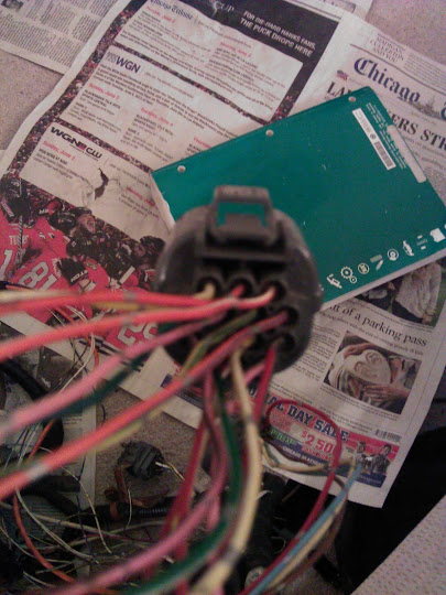
Plug 2-10pin
top row: B2=logic ground 2(brown/black) D14=primary heated o2(white) A26=logic ground 1(black/red)
middle row: B11=CYP sensor p-side(orange) B12=CYP ground m-side(white) B13=TDC ground p-side(orange/blue) B14=TDC ground m-side(white/blue)
bottom row: B15=CKP P ground(blue/greemn) B16=CKP M ground(blue/yellow) empty

Plug 3-4pin
Top: A3=injector 2(red) A1=injector 1(brown)
bottom: A2=injector 4(yellow) A5=injector 3(light blue)
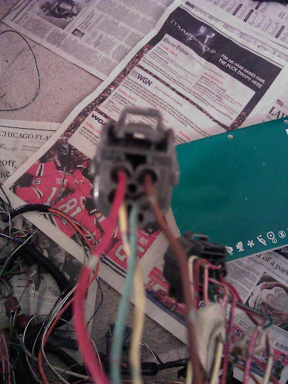
sorry for the shitty pics
Plug 1=14 pin (from left to right)
top row: A16=alternator control(white/yellow) A6-=primary o2 sensor heater control(orange/black) A4=vtec solenoid(orange/white)
2nd row: D21=sensor ground 1(green/blue) D17=MAP sensor(pink/white) D19=sensor voltage for MAP D6=vtec pressure switch(orange/blue)
3rd row: D11=throttle position sensor(pink/black) D22=sensor ground 2(green/white) D20=sensor voltage for TPS(yellow/white) A21=ignition control module(red/green)
bottom row: D15=intake air temp(red/yellow) D13=engine coolant temp sensor(red/white) D9=alternator FR charge signal(pink)
Plug 2-10pin
top row: B2=logic ground 2(brown/black) D14=primary heated o2(white) A26=logic ground 1(black/red)
middle row: B11=CYP sensor p-side(orange) B12=CYP ground m-side(white) B13=TDC ground p-side(orange/blue) B14=TDC ground m-side(white/blue)
bottom row: B15=CKP P ground(blue/greemn) B16=CKP M ground(blue/yellow) empty
Plug 3-4pin
Top: A3=injector 2(red) A1=injector 1(brown)
bottom: A2=injector 4(yellow) A5=injector 3(light blue)
sorry for the shitty pics
06-16-2013, 09:56 PM
#4
Honda-Tech Member
Join Date: May 2013
Location: Chicago
Posts: 6
Likes: 0
Received 0 Likes
on
0 Posts
i used this write up as a reference, although not all the colors matched
http://technet.ff-squad.com/wiring.obd1.htm
http://technet.ff-squad.com/wiring.obd1.htm
03-04-2014, 10:17 PM
#5
Honda-Tech Member

Join Date: Sep 2013
Posts: 4
Likes: 0
Received 0 Likes
on
0 Posts
I know this is an old post, I'm wireing in a obd1 z6 in to an obd2a car, which pin and plug on the engine harness is the right one for the iacv, don't see it listed on here?
Cheers
Cheers

Thread
Thread Starter
Forum
Replies
Last Post