

ITBs interest?

Thread Starter
Honda-Tech Member
Joined: Jun 2002
Posts: 5,273
Likes: 1
From: Traverse City, Michigan, USA
Im guaging interest on producing a universal(GSR, ITR, B16A) set of ITBs for boosted and NA applications...Price is not even an issue right now as we are still in EARLY prototype stages.
Glass impregnated Nylon *may* be the material used, this will keep the cost down tremendously(tooling will suck, but hey, what tooling doesnt?),will help with the weight department and thermal properties. Get this, Custom colors will be easy to mess with
So...who would be interested? Right now, B series Vtecs only...but as always, the more interest, the more products...
Honda-Tech Member
Joined: Aug 2002
Posts: 4,417
Likes: 0
From: ashEVILle, NC, USSR
<TABLE WIDTH="90%" CELLSPACING=0 CELLPADDING=0 ALIGN=CENTER><TR><TD>Quote, originally posted by simple4012 »</TD></TR><TR><TD CLASS="quote">the main problem with itb's is the problem of getting an accurate map signal. with boost the problem would be ten fold</TD></TR></TABLE>
(The whole issue of vacuum canisters aside)
No, the problem with ITBs is in NA form, in a speed density setup - anything over 25% throttle is almost identical to atmospheric pressure. You have to set your MAP pressure scalars very close together near WOT/atm and tune like hell to avoid flat spots and driveability problems. For NA ITB SD (Speed Density aka MAP sensor equipped) cars, utilizing one of the freeware Honda ECU tuning apps, it is easier to replace the MAP with the MAF from an 86-89 GM 5.0, as it is a linear output 0-5v device. Tuning is now flow dependant and not pressure - yay!
Boost alleviates that problem, as 3/4 of your throttle event is no longer acted upon as if it were WOT, with regards to MAP input. Feel free to retain the MAP sensor in boosted ITB setups.
I have a couple sets of 954RR ITBs sitting on my shelf. Cut stock intake flanges and radiator hose are the order of the day when it comes to mounting these and tuning runner length. I give props to tinker for fancy multicolored plastics, which will look bling and you kids will go crazy over - but here in the trailerpark we don't give a f*ck what things look like.
Thread Starter
Honda-Tech Member
Joined: Jun 2002
Posts: 5,273
Likes: 1
From: Traverse City, Michigan, USA
<TABLE WIDTH="90%" CELLSPACING=0 CELLPADDING=0 ALIGN=CENTER><TR><TD>Quote, originally posted by simple4012 »</TD></TR><TR><TD CLASS="quote">the main problem with itb's is the problem of getting an accurate map signal. with boost the problem would be ten fold</TD></TR></TABLE>
Not with a bolt-on plenum
Not with a bolt-on plenum
Trending Topics
Honda-Tech Member
Joined: Aug 2002
Posts: 4,417
Likes: 0
From: ashEVILle, NC, USSR
Eh?
That's creating a mental image that defeats the purpose of ITBs in my mind.
And, have you played with the idea of camming the ITB throttle pulley so that the last half of it's rotation is the last 25% of gas pedal travel? It would be a little more driveable, and throttling the pedal for boost would be a bit easier.
Joined: Sep 2002
Posts: 166
Likes: 0
From: Williamsburg, MI, USA
<TABLE WIDTH="90%" CELLSPACING=0 CELLPADDING=0 ALIGN=CENTER><TR><TD>Quote, originally posted by J. Davis »</TD></TR><TR><TD CLASS="quote">Eh?
That's creating a mental image that defeats the purpose of ITBs in my mind.
And, have you played with the idea of camming the ITB throttle pulley so that the last half of it's rotation is the last 25% of gas pedal travel? It would be a little more driveable, and throttling the pedal for boost would be a bit easier.</TD></TR></TABLE>
Ill toy with it, makes perfect sense. Kind of opposite of a bow and arrow if Im understanding what you are saying...
And for the map, could I not just tap into each TB(after the plate)with a vac line, and connect them all to the map sensor? just a thought, I cant see why it wouldnt work accurately(maybe thats my downfall )
*edit* haha, my brother is still online, this is Cody that posted up above
That's creating a mental image that defeats the purpose of ITBs in my mind.
And, have you played with the idea of camming the ITB throttle pulley so that the last half of it's rotation is the last 25% of gas pedal travel? It would be a little more driveable, and throttling the pedal for boost would be a bit easier.</TD></TR></TABLE>
Ill toy with it, makes perfect sense. Kind of opposite of a bow and arrow if Im understanding what you are saying...
And for the map, could I not just tap into each TB(after the plate)with a vac line, and connect them all to the map sensor? just a thought, I cant see why it wouldnt work accurately(maybe thats my downfall
)*edit* haha, my brother is still online, this is Cody that posted up above
Honda-Tech Member
Joined: Feb 2002
Posts: 4,746
Likes: 0
From: Southern California
<TABLE WIDTH="90%" CELLSPACING=0 CELLPADDING=0 ALIGN=CENTER><TR><TD>Quote, originally posted by Tinker219 »</TD></TR><TR><TD CLASS="quote">
Not with a bolt-on plenum </TD></TR></TABLE>
not quite. you want to take vacuum somewhere inbetween the head and the butterflies though for a good signal. with a bolt on plenum, you could use it for MAF, but not map. with map, u still need to source vacuum at a point where the intake charge has passed the butterflies already.
if you had itb's with a plenum on the end, and took signal from the plenum/airbox, that'd be the same as a conventional honda intake manifold, and taking a vacuum reading from the aem intake thats attached to it. wouldn't suffice.
you could take vacuum source from all 4 runners and run them to a properly sized canister.
Not with a bolt-on plenum
</TD></TR></TABLE>not quite. you want to take vacuum somewhere inbetween the head and the butterflies though for a good signal. with a bolt on plenum, you could use it for MAF, but not map. with map, u still need to source vacuum at a point where the intake charge has passed the butterflies already.
if you had itb's with a plenum on the end, and took signal from the plenum/airbox, that'd be the same as a conventional honda intake manifold, and taking a vacuum reading from the aem intake thats attached to it. wouldn't suffice.
you could take vacuum source from all 4 runners and run them to a properly sized canister.
Honda-Tech Member


Joined: Jan 2001
Posts: 4,749
Likes: 26
From: Portland, OR
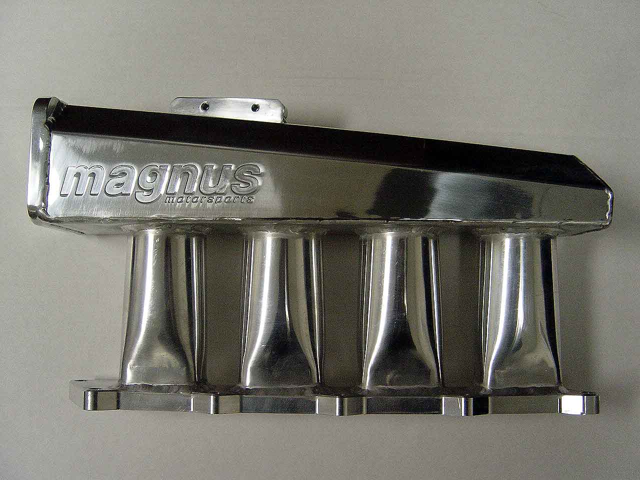
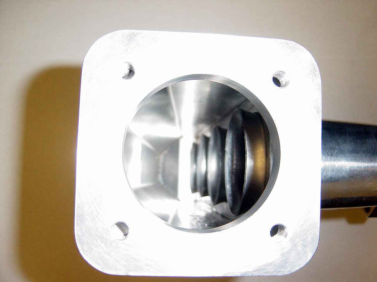
Some pictures of the Magnus Motorsports manifold for a 4g63.
Just eyeball the runners. No ITB's in this manifold, however im guessing this is something what tinker wants to do. Bolt a big plenum to some ITB's with volocity stacks. The magnus has the volocity stacks inside the plenum.
There is a few more pictures here:
http://www.roadraceengineering...ifold/
thanks,
liam
Thread Starter
Honda-Tech Member
Joined: Jun 2002
Posts: 5,273
Likes: 1
From: Traverse City, Michigan, USA
<TABLE WIDTH="90%" CELLSPACING=0 CELLPADDING=0 ALIGN=CENTER><TR><TD>Quote, originally posted by redlineb18 »</TD></TR><TR><TD CLASS="quote">
And for the map, could I not just tap into each TB(after the plate)with a vac line, and connect them all to the map sensor? </TD></TR></TABLE>
I ment post-butterfly. Itd be simple to do some nipple fittings w/Ts going to a Vac log where the Map sensor would get its reading. This is what I had planned on doing.
As for the Magnus IM, that is basically what its going to look like , but with the TBs on each stack. From what I have gathered, this is the BEST way to make power, boost or not. Am I mistaken with this? Because if I am, the project is mute, and Ill just make a badass thermoplastic Velocity Stack manifold
Joined: Apr 2003
Posts: 209
Likes: 0
From: Propaganda City, USA
Those velocity stacks just create turbulance in the plenum, they dont help accelerate the airflow. You could make a small radius in the transtion from plenum to runner to increase velocity.
Honda-Tech Member
Joined: Jan 2001
Posts: 4,749
Likes: 26
From: Portland, OR
<TABLE WIDTH="90%" CELLSPACING=0 CELLPADDING=0 ALIGN=CENTER><TR><TD>Quote, originally posted by Fac3Man »</TD></TR><TR><TD CLASS="quote">Those velocity stacks just create turbulance in the plenum, they dont help accelerate the airflow. You could make a small radius in the transtion from plenum to runner to increase velocity.
</TD></TR></TABLE>
That is what the golden eagle manifold is like. They have a small radius that transitions plenum to runner. And then each runner is tapered.
liam
</TD></TR></TABLE>
That is what the golden eagle manifold is like. They have a small radius that transitions plenum to runner. And then each runner is tapered.
liam

Honda-Tech Member
Joined: Jan 2003
Posts: 1,626
Likes: 0
From: Baltimore, MD
We just installed one of thoe Magnus tirds on a DSM, man is that thing poor craftsmanship. It is just like the one above. The vacuum ports on the back have weld slag all in them.

Honda-Tech Member
Joined: Jul 2001
Posts: 899
Likes: 0
I've put the magnus intake mani on two DSMs now and we've had nothing but good luck with them. If tapping out the ports on the bottom of the mani are difficult then there are bigger issues at hand.
I'd love to see a magnus style intake mani for hondas that is in that same price range.
I'd love to see a magnus style intake mani for hondas that is in that same price range.
Honda-Tech Member
Joined: May 2002
Posts: 15,814
Likes: 8
From: Dallas, TX, USA
<TABLE WIDTH="90%" CELLSPACING=0 CELLPADDING=0 ALIGN=CENTER><TR><TD>Quote, originally posted by Fac3Man »</TD></TR><TR><TD CLASS="quote">Those velocity stacks just create turbulance in the plenum, they dont help accelerate the airflow. You could make a small radius in the transtion from plenum to runner to increase velocity.
</TD></TR></TABLE>
I've always heard and read that velocity stacks raised off the floor of the plenum is the best way...
</TD></TR></TABLE>
I've always heard and read that velocity stacks raised off the floor of the plenum is the best way...