

Super T collector design for Garrett


Thread Starter
Joined: Jan 2003
Posts: 179
Likes: 0
From: Rochester, MN, us
I was having a lively discussion with another Honda tech member who thought my collectors were a horrible design. In his mind the tubes should be upright like the Full race collector(im assuming thats were his idea for what a collector should be and therefore all others are wrong as he has referenced the full race manifold) He felt that the four runners, when merging at the collector should be as close to upright as possible. This may be true in some applications, but I will tell you why I make mine the way I do and let you be the judge.
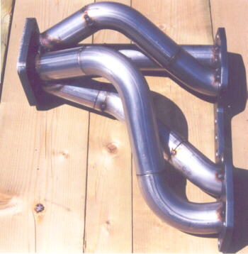
I designed my manifolds around the commonly available t3/t4 garret turbo. Now if you measure the opening to the turbine entrance and then take any commonly available t3 flange meant for header manufacturing and measure it, you will see that it is a full 1/4 bigger all the way around then the opening of the t3 garrett.(see pictures)
Now, if the runners were to enter near upright the exhaust gases would come straight down and ram right into that shelf, not a desirable effect on exhaust flow, would we not agree? Now by taking the runners and slanting them at an angle, we direct the exhuast pulses directly to the center of the turbine inlet(see picture). As you can clearly visualize, the exhaust gases will there for have minimal contact with the ridge and have smooth flow. I think perhaps too, he thought that since the pipes coming in were slanted, that the exhaust pulses would hit each other, but keep in mind exhaust pulses are spaced and do not enter the turbine at the same time.
I hope this answers some questions for him..he seemed awefully upset about my collector design...
Now, perhaps this design is not without flaws(one such flaw as that with the tubes slanted the exhaust pulses once they hit the inside of the turbine opening will deflect off the walls slightly, but this is much more desirable then having the pulses come down and ram off a ridge, read huge restriction and turbulence), but it is clearly the best option when you are creating a collector that merges all 4 pipes at the turbine entrance on a t3 such as the small opening of the garret ( some collectors merge the 4 into 1 pipe ahead of the turbine entrance, then only one pipe leads to the turbine entrance, that works good, but when you have 4 separate pipes all merging directly at the collector it is a different story..IMO)
You can get away with them more upright(such as the full race design) when dealing with a t4 as the entrance is much bigger to the turbine and thus you dont have the overlapping ledge to hinder flow...
These are just my personal opinions, nothing written in concrete, but I think the pictures speak a thousand words...
Dave

[Modified by SuperT, 6:13 AM 3/19/2003]
[Modified by SuperT, 6:19 AM 3/19/2003]
I designed my manifolds around the commonly available t3/t4 garret turbo. Now if you measure the opening to the turbine entrance and then take any commonly available t3 flange meant for header manufacturing and measure it, you will see that it is a full 1/4 bigger all the way around then the opening of the t3 garrett.(see pictures)
Now, if the runners were to enter near upright the exhaust gases would come straight down and ram right into that shelf, not a desirable effect on exhaust flow, would we not agree? Now by taking the runners and slanting them at an angle, we direct the exhuast pulses directly to the center of the turbine inlet(see picture). As you can clearly visualize, the exhaust gases will there for have minimal contact with the ridge and have smooth flow. I think perhaps too, he thought that since the pipes coming in were slanted, that the exhaust pulses would hit each other, but keep in mind exhaust pulses are spaced and do not enter the turbine at the same time.
I hope this answers some questions for him..he seemed awefully upset about my collector design...
Now, perhaps this design is not without flaws(one such flaw as that with the tubes slanted the exhaust pulses once they hit the inside of the turbine opening will deflect off the walls slightly, but this is much more desirable then having the pulses come down and ram off a ridge, read huge restriction and turbulence), but it is clearly the best option when you are creating a collector that merges all 4 pipes at the turbine entrance on a t3 such as the small opening of the garret ( some collectors merge the 4 into 1 pipe ahead of the turbine entrance, then only one pipe leads to the turbine entrance, that works good, but when you have 4 separate pipes all merging directly at the collector it is a different story..IMO)
You can get away with them more upright(such as the full race design) when dealing with a t4 as the entrance is much bigger to the turbine and thus you dont have the overlapping ledge to hinder flow...
These are just my personal opinions, nothing written in concrete, but I think the pictures speak a thousand words...
Dave
[Modified by SuperT, 6:13 AM 3/19/2003]
[Modified by SuperT, 6:19 AM 3/19/2003]


Thread Starter
Joined: Jan 2003
Posts: 179
Likes: 0
From: Rochester, MN, us
that would be really ideal...though, the flanges on the garrets are thick, the walls of the housing are not and would be extremely thin if you took out a 1/4 inch all the way around...you could taper it though and not thin it as much...that would be ideal...but as you know...99% of the customers out there will not get it machined out and will just use off the shelf parts...for which this collector design is in my humble opinion the best option...and I think my dyno numbers so far have shown that it is effective. I'll post up some dyno numbers of my 500rhwp toyota drag truck that had a similar design...flowed very nicely...
Dave
Dave
Thread Starter
Joined: Jan 2003
Posts: 179
Likes: 0
From: Rochester, MN, us
or why not make the flange smaller? get rid of the unknown factor of the ridge completely
I think thats what the disgruntled honda tech member was referring too when he said all race teams dont use this type, he is correct, they use true 4 into 1 that then has a one piece of pipe that enters the collector.(check out the hytech mani's, they use them) This is the most ideal and he would be correct. But those collectors add several hundred to the price and add little to the guy just wanting his 300-400-500hp honda...This collector has been dyno verified a couple years ago as being able to support 500+ hp.
The goal of this whole project and kit, has been fromt he beginning to offer an Affordable, high quality, power producing kit...are there better manifolds, hell yeah, are there ones that make more HP, hell yeah! But for the price, you get a kick *** looking(to most, not the haters obviously)manifold, made of premium materials, turbo, wastegate, downpipe etc etc for under 2000.00. That has been the goal and my dyno numbers are bearing the fruit of our labor. For the haters that dont like it...DONT BUT IT...its a demorcracy!
Dave
Thread Starter
Joined: Jan 2003
Posts: 179
Likes: 0
From: Rochester, MN, us
I had encounted this on my inlinePRO manifold and my Precision turbine housing. I just matched up the flanges together and all was happy.
Trending Topics
Thread Starter
Joined: Jan 2003
Posts: 179
Likes: 0
From: Rochester, MN, us
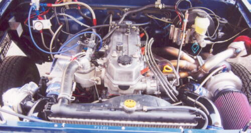
Here is a picture of a similar collector design made here at super t motorsports about three years ago. This motor was making 500rwhp on a "small t4"(60-1)
This collector design of mine is not new and has been tested years ago...
This truck went the entire race season without a single failure of any sort!(over 100passes at 11 racing events!) The last race of the year the head gasket started leaking...You would not believe how many so called "experts" told me the 22r could never possibly hold that kind of HP...
this motor is a SOHC cam 2 valve design that even fully ported flows less then a stock b series head, yet I was making 5 times the stock hp(was rated stock at 115 crankshaft Hp)!
[Modified by SuperT, 6:50 AM 3/19/2003]
Thread Starter
Joined: Jan 2003
Posts: 179
Likes: 0
From: Rochester, MN, us
Thanks ffgeoff, I hope you didn't think I was degrading your manifold...I wasn't I was just defending myself against someone on here who has taken a particular interest in my collector...
Im trying to keep it clean as possible...
Dave
Im trying to keep it clean as possible...
Dave
Honda-Tech Member
Joined: May 2001
Posts: 4,719
Likes: 0
From: FULL RACE, AZ, USA
you might want to consider getting or making different size flanges. That is the reason why i ask customers what turbos they are running.
Thread Starter
Joined: Jan 2003
Posts: 179
Likes: 0
From: Rochester, MN, us
Yes, I was considering that...As you can see, if I were to get some custom machined flanges with smaller openings, I wouldn't have the gap on the sides that needs to be first filled in with MIG and then gone over with TIG...it would just cut the process time down a shitload as well as producing a cleaner looking manifold...both of which would be desirable...we'll get there...it takes time as you know...
Dave
Dave
Thread Starter
Joined: Jan 2003
Posts: 179
Likes: 0
From: Rochester, MN, us
No, actually they dont, do research before you post information...Exhaust pulses travel at near supersonic speeds and as such, as long as all runners are within approx. 6 inches overall length of each other, will not hit each other...all the runners on this manifold are within a couple of inches of each other. Do the math on exhaust velocity v. cylinder firing timing and occurance...
You have posted very derogatory uninformed, biased posts on my last three threads only to discredit me...
None of them have been factual, just contempt and hatred...
Please refrain from posting on my threads unless you have something credible to post...
Thankyou
Dave
You have posted very derogatory uninformed, biased posts on my last three threads only to discredit me...
None of them have been factual, just contempt and hatred...
Please refrain from posting on my threads unless you have something credible to post...
Thankyou
Dave

Thread
Thread Starter
Forum
Replies
Last Post
earl
Forced Induction
2
Oct 24, 2001 06:09 PM