


 Mar 25, 2015, 09:52 AM
Last edit by: IB Advertising
See related guides and technical advice from our community experts:
Browse all: Engine and Powertrain
- Honda Accord: How to remove TPS Throttle Position Sensor
Step by step instructions for do-it-yourself repairs.
Browse all: Engine and Powertrain

The Official Honda TPS wiring and calibration thread
Thread Starter
Honda-Tech Member
Joined: Feb 2002
Posts: 1,210
Likes: 4
From: MIAMI
Throttle position sensor (TPS) - ( ECU Code #7 )
The Honda TPS sensor (throttle position sensor) monitors the throttle position and sends that signal to the ECU. The computer uses the TPS signal along with many other sensor inputs such as: MAP, Air Temp, Barometric Pressure, and RPM to maintain proper engine response and idle performance. Basically it is how your ECU knows your throttle input.
Electrically, Honda TPS sensors are basic variable resistors. They have a given resistance at rest and as the throttle is opened, the resistance is lowered and more voltage is sent to the ECU. This should result in a smooth increase in voltage on the output wire as the throttle is opened. The operating voltage is from 0.5v DC at rest (closed) to 4.5v DC at wide open.

Symptoms of bad TPS
Check Engine light - Code #7
Symptoms of bad TPS include hesitation/stumbling/misfiring at low RPM and poor fuel economy. It can also cause problems only at a specific throttle position. For example stumbling/hesitation only at 25% throttle but otherwise ok.
Sensor Wiring
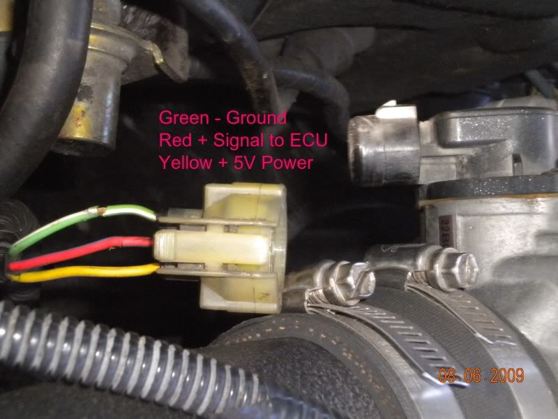
The Honda TPS has 3 wires and you can easily check with a regular DC voltage meter or multimeter.
The GREEN wire is DC - negative ground
The RED wire is DC + Signal output to the ECU. (This is the wire we must measure for calibration)
The YELLOW wire is 5v DC + positive and should always read 5V when the key is in the ignition.
Testing TPS Voltage
Check ground - (Green)
1. Set meter to continuity ( -->I-- ). Some meters have (((( symbol which will beep when there is continuity.
2. Connect negative lead of meter to battery ground.
3. Connect positive lead to green wire. Verify that the wire has a good ground.
***Key must be in the ignition to the ACC position to test power and signal***
Check 5V Power + (Yellow)
1. Set meter to DC Voltage.
2. Connect negative lead to battery ground
3. Connect positive lead to yellow wire. Verify 5v DC +
Check TPS Signal output + (Red)
1. Set meter to DC Voltage.
2. Connect negative lead to battery ground
3. Connect positive lead to red wire. You should see approx 0.5v when closed and 4.5v when you fully open the throttle body.
4. Check the TPS voltage for “Dead Spots”. Throughout the range of movement the voltage should increase smoothly and steadily without any sudden voltage gaps, drops, or spikes .
**If your voltage is backwards (4.5v closed and .5v open) then your TPS wiring is incorrect. Reverse the position of green and yellow wires.**
**Another common mistake is reversing the TPS and MAP plugs. Make sure the correct plug is connected**
**You may have to reset the ECU to clear the CEL code 7, if you cycled the key with the TPS disconnected during testing**
(to reset ecu, disconnect neg battery cable. Remove "Hazard" 10A fuse from under hood fuse box. Count to 20. Insert fuse and reconnect battery.
TPS Removal
1. You can Remove throttle body - Disconnect intake, throttle cable, wiring plugs, and vacuum lines. Remove (2) 12mm bolts and (2) 12mm nuts. Just remember a new TB gasket.
2. To Remove TPS - some have (2) Torx screws holding on the TPS. For earlier years there are machine screws that you'll have to cut a slot in the screw head and remove with a flathead screwdriver. A dremel with a cut off wheel of a hacksaw blade work well to cut the slots.
TPS Installation
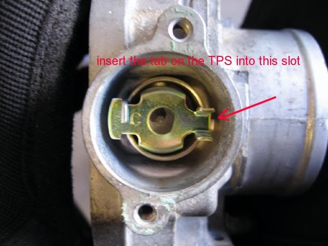
1. Replace TPS - insert tab on TPS into slot on the TB and turn counter-clockwise until the bolt holes line up. Tighten the screws finger tight but loose enough where you can swivel it.
2. Reinstall throttle body and connect TPS wiring plug.
3. Connect negative meter lead to battery ground.
4. Connect positive meter lead to red signal wire and check voltage.
5. Turn TPS until you get a reading of 0.5v DC and tighten screws.
6. Verify correct voltage output. (0.5v closed and 4.5v open)

-
*********DPFI (dual injector setup) TPS**********
The TPS Sensor on the DPFI version is different than all the other types of MPFI Throttle Position Sensors. The DPFI version rotates in the opposite direction as all the MPFI versions. Because it rotates in a opposite direction, the wiring is reversed to account for this change. *If you are swapping to a MPFI setup or B-Series, you must reverse the position of the yellow and green wires.

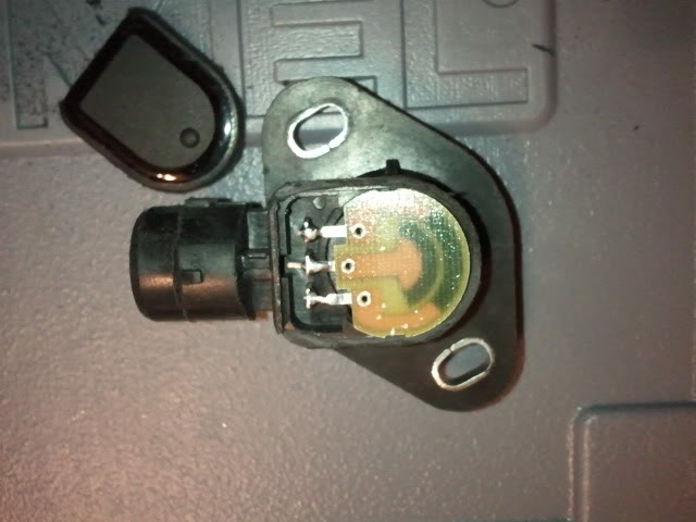
For a replacement sensor you must get a TPS for the DPFI setup because the others will not work directly. Others have disassembled the sensors and talked about some possible repairs on these threads, but nothing too substantial.
https://honda-tech.com/forums/showth...ge=2&t=2944614
Or you could buy a new one from omni power
http://thmotorsports.com/omni_power/.../i-403927.aspx
The Honda TPS sensor (throttle position sensor) monitors the throttle position and sends that signal to the ECU. The computer uses the TPS signal along with many other sensor inputs such as: MAP, Air Temp, Barometric Pressure, and RPM to maintain proper engine response and idle performance. Basically it is how your ECU knows your throttle input.
Electrically, Honda TPS sensors are basic variable resistors. They have a given resistance at rest and as the throttle is opened, the resistance is lowered and more voltage is sent to the ECU. This should result in a smooth increase in voltage on the output wire as the throttle is opened. The operating voltage is from 0.5v DC at rest (closed) to 4.5v DC at wide open.
Symptoms of bad TPS
Check Engine light - Code #7
Symptoms of bad TPS include hesitation/stumbling/misfiring at low RPM and poor fuel economy. It can also cause problems only at a specific throttle position. For example stumbling/hesitation only at 25% throttle but otherwise ok.
Sensor Wiring
The Honda TPS has 3 wires and you can easily check with a regular DC voltage meter or multimeter.
The GREEN wire is DC - negative ground
The RED wire is DC + Signal output to the ECU. (This is the wire we must measure for calibration)
The YELLOW wire is 5v DC + positive and should always read 5V when the key is in the ignition.
Testing TPS Voltage
Check ground - (Green)
1. Set meter to continuity ( -->I-- ). Some meters have (((( symbol which will beep when there is continuity.
2. Connect negative lead of meter to battery ground.
3. Connect positive lead to green wire. Verify that the wire has a good ground.
***Key must be in the ignition to the ACC position to test power and signal***
Check 5V Power + (Yellow)
1. Set meter to DC Voltage.
2. Connect negative lead to battery ground
3. Connect positive lead to yellow wire. Verify 5v DC +
Check TPS Signal output + (Red)
1. Set meter to DC Voltage.
2. Connect negative lead to battery ground
3. Connect positive lead to red wire. You should see approx 0.5v when closed and 4.5v when you fully open the throttle body.
4. Check the TPS voltage for “Dead Spots”. Throughout the range of movement the voltage should increase smoothly and steadily without any sudden voltage gaps, drops, or spikes .
**If your voltage is backwards (4.5v closed and .5v open) then your TPS wiring is incorrect. Reverse the position of green and yellow wires.**
**Another common mistake is reversing the TPS and MAP plugs. Make sure the correct plug is connected**
**You may have to reset the ECU to clear the CEL code 7, if you cycled the key with the TPS disconnected during testing**
(to reset ecu, disconnect neg battery cable. Remove "Hazard" 10A fuse from under hood fuse box. Count to 20. Insert fuse and reconnect battery.
TPS Removal
1. You can Remove throttle body - Disconnect intake, throttle cable, wiring plugs, and vacuum lines. Remove (2) 12mm bolts and (2) 12mm nuts. Just remember a new TB gasket.
2. To Remove TPS - some have (2) Torx screws holding on the TPS. For earlier years there are machine screws that you'll have to cut a slot in the screw head and remove with a flathead screwdriver. A dremel with a cut off wheel of a hacksaw blade work well to cut the slots.
TPS Installation
1. Replace TPS - insert tab on TPS into slot on the TB and turn counter-clockwise until the bolt holes line up. Tighten the screws finger tight but loose enough where you can swivel it.
2. Reinstall throttle body and connect TPS wiring plug.
3. Connect negative meter lead to battery ground.
4. Connect positive meter lead to red signal wire and check voltage.
5. Turn TPS until you get a reading of 0.5v DC and tighten screws.
6. Verify correct voltage output. (0.5v closed and 4.5v open)
-
*********DPFI (dual injector setup) TPS**********
The TPS Sensor on the DPFI version is different than all the other types of MPFI Throttle Position Sensors. The DPFI version rotates in the opposite direction as all the MPFI versions. Because it rotates in a opposite direction, the wiring is reversed to account for this change. *If you are swapping to a MPFI setup or B-Series, you must reverse the position of the yellow and green wires.
For a replacement sensor you must get a TPS for the DPFI setup because the others will not work directly. Others have disassembled the sensors and talked about some possible repairs on these threads, but nothing too substantial.
https://honda-tech.com/forums/showth...ge=2&t=2944614
Or you could buy a new one from omni power
http://thmotorsports.com/omni_power/.../i-403927.aspx
Last edited by gringo7718; Oct 10, 2012 at 07:30 PM.
Honda-Tech Member
Joined: Feb 2006
Posts: 3
Likes: 0
From: wilmington, nc, usa
Also, the tps calibration should really be done with the car warmed up. It probably won't make too much of a difference, but that is what all my dealership grease-monkey friends have told me.
this is helpful, but do you know how to adjust the base idle screw on the throttle body? i found conflicting info. mine was adjusted by previous owner and it took quite a bit to sort it out
Honda-Tech Member
Joined: Apr 2010
Posts: 41
Likes: 0
From: Wisconsin
Awesome info, this is very helpful! There is a lot of conflicting information about how to calibrate a tps but this definitely clears it up. This should be added to the FAQ section for sure.

Trending Topics
Honda-Tech Member
Joined: Dec 2011
Posts: 11
Likes: 0
just swap a h23a into my ek and turns out the tps connector doesnt snap onto the tps itself and is been held on by zip ties, i know i know hahahah does any one got a spare connector they wanna get rid of??? or i heard i can use any other connector and does not have to be off an H...
Honda-Tech Member
Joined: Oct 2008
Posts: 14
Likes: 0
From: athens, Greece
hi, i hate to spoil the thread, but i really need help in something and i have a feeling i am in the right place.
I own a 1991 civic with a d15b2 mpfi swap which i did 3 years ago myself. I had to replace the tps sensor (at the time of the swap) because it was broken, so i adjusted it to 0.5v at closed tb and aprox 4.5v at wot ,i run perfectly. Thing is i recently started getting code 7 very often , some times even 5 times in a route from home to work, so i though i should re-adjust it. To my surprise i got 0.5volts at closed tb and 4.2volts at wide open tb,if i adjusted it based on 4.5vot it would be off at closed tb, i know its not the tps because i have tested 3 of them, so what i did was that i removed the tps plug and put the negative of the voltmeter to the left contact of the plug and the possitive to the middle one (with the key to position 2) and i got 4.85 volts instead of 5volts.
so the question is ..where did these vital 0.15 volts go and how can i solve this? where does the 5volt signal come from and whats its route? is there a way to test the source of the signal , see if there is something wrong with the wiring? i am really stuck and i need help!


With the car off the voltage may be low, that is perfectly normal. Start the car and I bet it's 5.0 or higher. Your battery or grounds may be the problem as well.
Honda-Tech Member
Joined: Oct 2008
Posts: 14
Likes: 0
From: athens, Greece
alright i just came back from the car..and i did the following..i removed the third plug from the ecu(with the car not working) i measured the side cables of the tps plug at the 200ohm scale, and it came up with 2.7ohms..any ideas?
Honda-Tech Member
Joined: Oct 2008
Posts: 14
Likes: 0
From: athens, Greece
i am going to go ahead and get a new tps, but those ebay ones look really fake quality, is there anyone selling original tps?or a good brand?
I like the tuna here
Joined: May 2004
Posts: 1,564
Likes: 4
From: Raleigh, NC
Also, this might be a pretty stupid question, but if you wanted to run a leaner A/F mixture, could that be accomplished cheaply by adjusting the TPS *very slightly* so instead of say 1.1 volts at 25% throttle, it says only 1 volt?
Honda-Tech Member
Joined: Oct 2008
Posts: 14
Likes: 0
From: athens, Greece
Bottomline is that i am looking for a new tps, there are tps sensors on ebay that start from 5$ shiped to 50$ shipped..point is which should i trust?any good brands?a link to the right direction would help , i just need to solve this problem forever and forget about the word "tps"
Honda-Tech Member
Joined: Oct 2008
Posts: 14
Likes: 0
From: athens, Greece
i think the ecu will find out what you did and will give you a code, just like what it did with mine, my tps is 0.24volts off and i keep seeing check engine all the time
Honda-Tech Member
Joined: Jul 2012
Posts: 24
Likes: 0
"Or you could buy a new one from omni power "
I ordered one from omni power and received the wrong part. It was the
same TPS that everyone else was selling, the one that mounts and turns in the wrong direction! I bought 2 off ebay and and again received the same wrong parts. Apparently, everyone on ebay is using the same faulty database. There is no way the Honda TPS (DPFI one) fits like 30 other Honda's, some well past the year 2000! So frustrating! I finely got one from a junk yard, but now it is has started to fail as well! Also tried fixing one of the old ones, but they used different size brushes then the newer ones.

Trial User
Joined: Nov 2012
Posts: 2
Likes: 0
I need some help.
I have a 91 accord wagon, trying to calibrate the tps.
at idle I get 0 volts (up to about .33 but no more)
at wot I get about 3.1 volts
I've tested the plug and am getting 5 volts
throttle cable is adjusted so that when the pedal is on the floor it just hits the stop
I've looked at the transmission wire and adjusted it a bit with no change in wot voltage.
I've tried two different tps and both give the same voltages.
Anyone have any ideas?
thanks for your help! - Ed
Trial User
Joined: Nov 2012
Posts: 2
Likes: 0
Just to update in case some else has the same issue....
I didn't have the sensor seated properly, hence the lower voltages.
I had a cheap meter, so readings fluctuated too much.
New meter and a properly seated sensor = success!
I've seen some say to set the idle voltage at .48, and others at .5v?
What is the effect of setting it at .48? Does that alter A/F ratios and lean it out just a little?

Honda-Tech Member
Joined: Nov 2005
Posts: 24
Likes: 0
From: Los Angeles, CA
Question, I am having problems with my tps. The car is a 91 hatch with a b16a swap. according to the multimeter I am only getting .9 volts to the tps. on the 5 volt lead. ground is good. The signal wire is reading .09v closed and .15v wot. Where do I find the source of the 5 volts? I believe that is my problem. I have looked at pinouts, but only find the tps signal wire from the ecu.
Thanks in advance.
Thanks in advance.