


*Help with PF mirror diagrams*

Thread Starter
Honda-Tech Member
Joined: May 2009
Posts: 220
Likes: 0
From: san jose
Finally found the time to put this thread together. My pf mirror project is for a 99 civic EX. After comparing all diagrams available and much confusion, I am only down to 2 problems now:
Problem (1): How should I wire the two white and 2 black wires coming from the mirrors?
Problem (2): If I need a + and - source, is running wire to the battery my only option? Couldn't I find other sources like the kicker panel? Where are the stock mirrors getting their power from? Why can't I use the same + and - source from the stock mirrors for my new mirrors?
Thanks in advance.
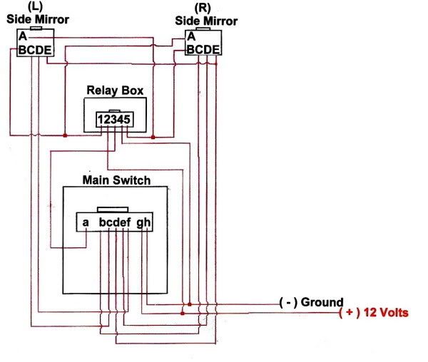
This diagram was posted on ej8squad. It is the best one I have seen so far.
Problem (1): How should I wire the two white and 2 black wires coming from the mirrors?
Problem (2): If I need a + and - source, is running wire to the battery my only option? Couldn't I find other sources like the kicker panel? Where are the stock mirrors getting their power from? Why can't I use the same + and - source from the stock mirrors for my new mirrors?
Thanks in advance.
This diagram was posted on ej8squad. It is the best one I have seen so far.
Last edited by dgerej2; Dec 30, 2009 at 03:04 PM.
Thread Starter
Honda-Tech Member
Joined: May 2009
Posts: 220
Likes: 0
From: san jose
The switch needs a + and - source as shown in the ej8squad diagram, so I'm pretty sure the ORANGE/white and BLACK wires could be my link to the battery. In stock form the switch does not link to the battery, my guess is the passenger side mirrors linked to the battery. With the power fold mirror set up, my guess is the switch (g and h) need to reach the battery.


Finally found the time to put this thread together. My pf mirror project is for a 99 civic EX. After comparing all diagrams available and much confusion, I am only down to 2 problems now:
Problem (1): Since the passenger side panel wiring has 2 unused wires (5. ORANGE/white) and (6. BLACK), are they a + and - source? If so, can I attach the + and - from the relay to these?
Problem (1): Since the passenger side panel wiring has 2 unused wires (5. ORANGE/white) and (6. BLACK), are they a + and - source? If so, can I attach the + and - from the relay to these?
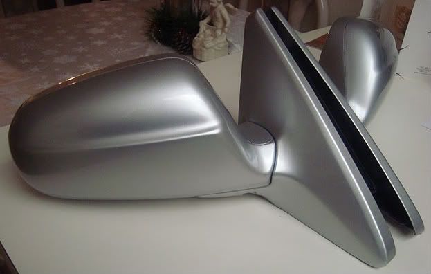
Three questions, first two are relevant one to your current project, then one to settle my curiosity:
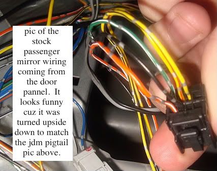
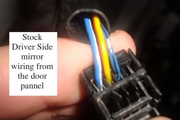
1. Where are the wires that drive the DRIVER's side 'power fold' feature in this picture:
Is that them on the top left? Did you remove them for the photo? (Confusing!) If they are not there, then you have an even bigger problem: Your driver's side mirror is not 'power folding' -- you were sold a dud. Bleh.
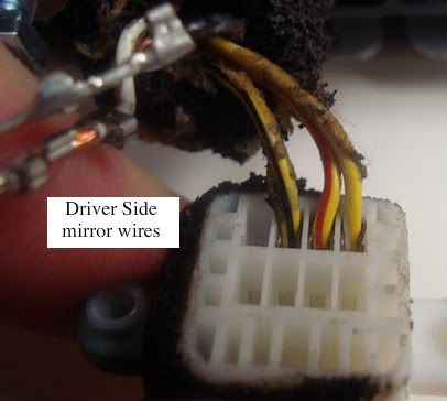
2. What is the blob of solder on the wire in this picture?
Is that like that from the factory? Yikes! Better cover that up with heat-shrink tubing to be safe -- you don't want your mirror catching on fire if there's a short.
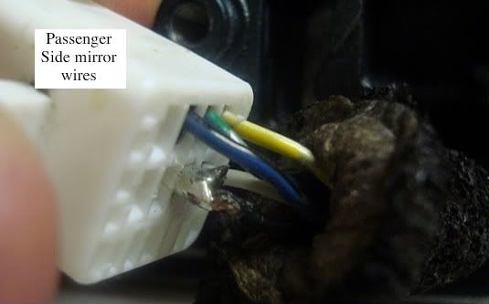
3. Does your original non-folding PASSENGER side mirror have the wires on the mirror side for the heated feature? If so, then one of your mirrors is probably heated... not that you have any way to control the heating. Interesting nonetheless.
Problem (2): What do I do with the left over 2 white and 2 black wires coming from the mirrors? Should I just pin these into the white terminals?
This diagram was posted on ej8squad. It is the best one I have seen so far.
The switch needs a + and - source as shown in the ej8squad diagram, so I'm pretty sure the ORANGE/white and BLACK wires could be my link to the battery. In stock form the switch does not link to the battery, my guess is the passenger side mirrors linked to the battery. With the power fold mirror set up, my guess is the switch (g and h) need to reach the battery.
Thread Starter
Honda-Tech Member
Joined: May 2009
Posts: 220
Likes: 0
From: san jose
Before answering your questions, I want to make sure you are aware of what I’m working with. The mirror internals & wiring are from the Honda JDM. I bought these power folding mirrors from www.j-specialty.com. Of course, RHD mirrors have a different angle and the convex glass is on the opposite side compared to LHD. Solution, I bought a set of non-power fold replica ctr mirrors. The bases and glass was swapped. The end product is a set of power adjustable & folding "non-usdm style" aka "ctr" mirrors that give no vision problems for me in my LHD civic.
Answers to your questions.
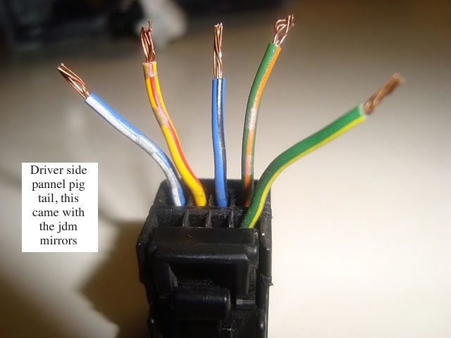
1. The driver side black and white mirror switches you see de-pinned do belong to the jdm mirror housings. They are de-pinned because I’m not sure how to pin them correctly. Not sure on correct location for these two wires and the other black and white wire belonging to the passenger side mirrors. The other black and white wires are pinned because I wanted to make sure they fit with the soldered black wire being so big.
2. After reading your heated power fold DIY, I realized that cutting wire is unnecessary and not recommended. The black wire you see was my first de-pin victim. It was salvaged, but suffered some wounds. My buddy soldered it for me, It came out very plump IMO.
3. No, I never realized that the ORANGE/white and BLACK wires running up the passenger side door lead to nothing. The mirror white terminal has only 3 pins sticking out on the top row. WTF?
4. The left over black and white wires questions section was unfinished by me. When I de-pinned my white box mirror terminals, I lost my diagrams and had to ask for help to re-pin the terminals. With your help on a previous thread, 6 locations made sense thanks to an OEM diagram. Now I have 4 left over wires, 2 white and 2 black. They are "left over" because I dont know if they should be pinned like this:
[w][ ][ ][ ] <-Driver [b][ ][ ][ ] <- Passenger side
[b] [ ][ ][ ] <-- Side [w][ ][ ][ ]
Or
[b][ ][ ][ ] <- Driver [b][ ][ ][ ] <- Passenger side
[w][ ][ ][ ] <-- Side [w][ ][ ][ ]
Etc, ect. A total of 4 different white and black combinations.
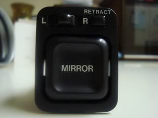
I did realized the switch looks different on the diagram you say is for 5th gens (It only has one horizontal row instead of two). I have heard of so many different switches and relays existing. However, the switch shares very similar characteristics with my switch. The a. on the switch is all by it self just like the BLACK/yellow wire in my switch. The g. and h. are paired together just like a + and - in the j-specialty diagram. h. is BLACK which is likely to be used for ground, while g. is BLUE/yellow and I’m guessing it’s the +. This is another reason why I came up with the ORANGE/white wire being + and the BLACK wire being -(PS OEM door panel mirror wiring). Isn't a solid black wire usually used for ground? The remaining bcdef spaces = 5 spaces just like my switch.
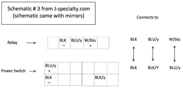
Please look at the J-specialty diagram that came with my jdm mirrors.
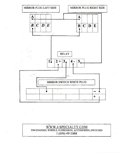
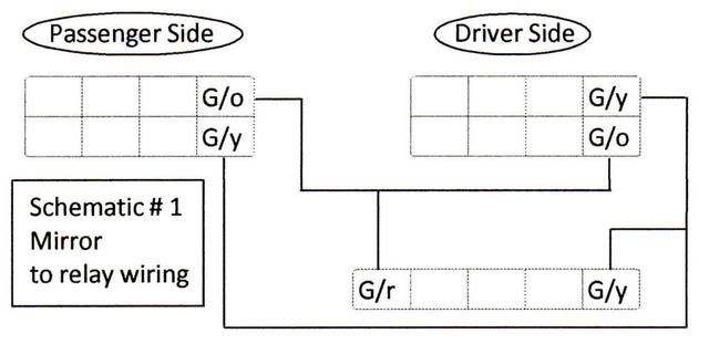
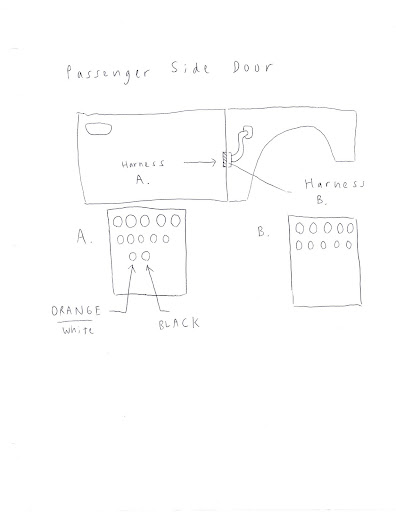
I have compared the “5th gen diagram to the J-specialty diagram and they are exactly identical. (Except one is upside down) The Honda-Tech diagram does not match up to these two diagrams. I have included my hand drawn diagram that I feel is perfect. I believe everything excluded in my hand drawn diagram should be wired to the original cut OEM wiring. My shorthand for blue is bu instead of the usual blu.

A few things to add. I have extra wiring with pins attached. Should the fatty soldered wire be replaced? I have my friends soldering kit, should soldering be done as thin as possible to avoid shorts? I am no expert in auto/soldering/wiring tech.

If I need a + and - source, is running wire to the battery my only option? Couldn't I find other sources like the kicker panel? Where are the stock mirrors getting their power from? Why can't I use the same + and - source from the stock mirrors for my new mirrors? My heads gonna explode!
This thread is posted on 3 different sites in hopes of finding answers. In total, this thread has over 213 views. I have not had much help, I am very grateful for all support and advice from anyone. Thx
PS. This link was pmed to me via ej8squad. It has some useful stuff IMO. It seems his wiring does not match his diagram though.
http://www.hondatech.co.uk/forum/vie...ghlight=#11137
Answers to your questions.
1. The driver side black and white mirror switches you see de-pinned do belong to the jdm mirror housings. They are de-pinned because I’m not sure how to pin them correctly. Not sure on correct location for these two wires and the other black and white wire belonging to the passenger side mirrors. The other black and white wires are pinned because I wanted to make sure they fit with the soldered black wire being so big.
2. After reading your heated power fold DIY, I realized that cutting wire is unnecessary and not recommended. The black wire you see was my first de-pin victim. It was salvaged, but suffered some wounds. My buddy soldered it for me, It came out very plump IMO.
3. No, I never realized that the ORANGE/white and BLACK wires running up the passenger side door lead to nothing. The mirror white terminal has only 3 pins sticking out on the top row. WTF?
4. The left over black and white wires questions section was unfinished by me. When I de-pinned my white box mirror terminals, I lost my diagrams and had to ask for help to re-pin the terminals. With your help on a previous thread, 6 locations made sense thanks to an OEM diagram. Now I have 4 left over wires, 2 white and 2 black. They are "left over" because I dont know if they should be pinned like this:
[w][ ][ ][ ] <-Driver [b][ ][ ][ ] <- Passenger side
[b] [ ][ ][ ] <-- Side [w][ ][ ][ ]
Or
[b][ ][ ][ ] <- Driver [b][ ][ ][ ] <- Passenger side
[w][ ][ ][ ] <-- Side [w][ ][ ][ ]
Etc, ect. A total of 4 different white and black combinations.
I did realized the switch looks different on the diagram you say is for 5th gens (It only has one horizontal row instead of two). I have heard of so many different switches and relays existing. However, the switch shares very similar characteristics with my switch. The a. on the switch is all by it self just like the BLACK/yellow wire in my switch. The g. and h. are paired together just like a + and - in the j-specialty diagram. h. is BLACK which is likely to be used for ground, while g. is BLUE/yellow and I’m guessing it’s the +. This is another reason why I came up with the ORANGE/white wire being + and the BLACK wire being -(PS OEM door panel mirror wiring). Isn't a solid black wire usually used for ground? The remaining bcdef spaces = 5 spaces just like my switch.
Please look at the J-specialty diagram that came with my jdm mirrors.
I have compared the “5th gen diagram to the J-specialty diagram and they are exactly identical. (Except one is upside down) The Honda-Tech diagram does not match up to these two diagrams. I have included my hand drawn diagram that I feel is perfect. I believe everything excluded in my hand drawn diagram should be wired to the original cut OEM wiring. My shorthand for blue is bu instead of the usual blu.
A few things to add. I have extra wiring with pins attached. Should the fatty soldered wire be replaced? I have my friends soldering kit, should soldering be done as thin as possible to avoid shorts? I am no expert in auto/soldering/wiring tech.
If I need a + and - source, is running wire to the battery my only option? Couldn't I find other sources like the kicker panel? Where are the stock mirrors getting their power from? Why can't I use the same + and - source from the stock mirrors for my new mirrors? My heads gonna explode!
This thread is posted on 3 different sites in hopes of finding answers. In total, this thread has over 213 views. I have not had much help, I am very grateful for all support and advice from anyone. Thx
PS. This link was pmed to me via ej8squad. It has some useful stuff IMO. It seems his wiring does not match his diagram though.
http://www.hondatech.co.uk/forum/vie...ghlight=#11137
Last edited by dgerej2; Dec 30, 2009 at 10:44 AM.
Oh, right, right .... I forgot that there are two different "styles" of connectors for the mirror switches for 6th Gen! More later ...
Before answering your questions, I want to make sure you are aware of what I�m working with. The mirror internals + wiring are from the Honda JDM. I bought these power folding mirrors from www.j-specialty.com. Of course, RHD mirrors have a different angle and the convex glass is on the opposite side compared to LHD. Solution, I bought a set of non-power fold replica ctr mirrors. The bases and glass was swapped. The end product is a set of power adjustable & folding "non-usdm style" aka "ctr" mirrors that give no vision problems for me in my LHD civic.

Answers to your questions.
1. The driver side black and white mirror switches you see de-pinned do belong to the jdm mirror housings. They are de-pinned because I�m not sure how to pin them correctly. Not sure on correct location for these two wires and the other black and white wire belonging to the passenger side mirrors. The other black and white wires are pinned because I wanted to make sure they fit with the soldered black wire being so big.
2. After reading your heated power fold DIY, I realized that cutting wire is unnecessary and not recommended. The black wire you see was my first de-pin victim. It was salvaged, but suffered some wounds. My buddy soldered it for me, It came out very plump IMO.
3. No, I never realized that the ORANGE/white and BLACK wires running up the passenger side door lead to nothing. The mirror white terminal has only 3 pins sticking out on the top row. WTF?
.... Actually, on sober second thought ... I bet they end at the door connector. But, you can still use them, as it's here that you can connect your GRN/ORG and GRN/YEL for the 'power fold' feature.
EDIT: Actually, I bet that the BLK is going to be a generic ground wire for other electrical components in the door, too. It might not be safe to use this wire as a substitute until you've verified that nothing else is being grounded through this same wire.
4. The left over black and white wires questions section was unfinished by me. When I de-pinned my white box mirror terminals, I lost my diagrams and had to ask for help to re-pin the terminals. With your help on a previous thread, 6 locations made sense thanks to an OEM diagram. Now I have 4 left over wires, 2 white and 2 black. They are "left over" because I dont know if they should be pinned like this:
[w][ ][ ][ ] <-Driver [b][ ][ ][ ] <- Passenger side
[b] [ ][ ][ ] <-- Side [w][ ][ ][ ]
Or
[b][ ][ ][ ] <- Driver [b][ ][ ][ ] <- Passenger side
[w][ ][ ][ ] <-- Side [w][ ][ ][ ]
Etc, ect. A total of 4 different white and black combinations.
[w][ ][ ][ ] <-Driver [b][ ][ ][ ] <- Passenger side
[b] [ ][ ][ ] <-- Side [w][ ][ ][ ]
Or
[b][ ][ ][ ] <- Driver [b][ ][ ][ ] <- Passenger side
[w][ ][ ][ ] <-- Side [w][ ][ ][ ]
Etc, ect. A total of 4 different white and black combinations.
I did realized the look of the switch looks different on the diagram you say is for 5th gens. I have heard of so many different switches and relays existing. However, the switch shares very similar characteristics with my switch. The a. on the switch is all by it self just like the BLACK/yellow wire in my switch. The g. and h. are paired together just like a + and - in the j-specialty diagram. H. is BLACK which is likely to be used for ground, while h. is BLUE/yellow and I�m guessing it�s the +. This is another reason why I came up with the ORANGE/white wire being + and the BLACK wire being -(PS OEM door panel mirror wiring). The remaining bcdef spaces = 5 spaces just like my switch.
Please look at the J-specialty diagram that came with my jdm mirrors.
Please look at the J-specialty diagram that came with my jdm mirrors.
I have compared the �5th gen diagram to the J-specialty diagram and they are exactly identical. (Except one is upside down) The Honda-Tech diagram does not match up to these two diagrams. I have included my hand drawn diagram that I feel is perfect. I believe everything excluded in my hand drawn diagram should be wired to the original cut OEM wiring. My shorthand for blue is bu instead of the usual blu.
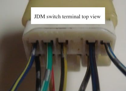
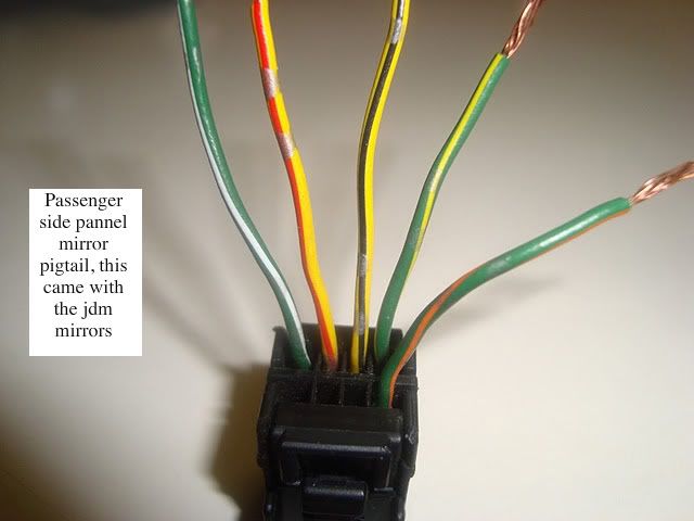
First off, let's get some terminology correct before we begin: The TOP side to a connector is ALWAYS going to be the side with the clip - ie., the spot on the connector you depress to remove it. Next, understand that the numbering of the pin location is from left to right with the clip at the top, looking at the connector from the wire side. For example, in the photo you provide here:
The wiring order goes like this:
______|----|______
[1][2][-][-][3][4]
[5][6][7][8][9][10]
[1](Blank)
[2]BLK/YEL
[3]YEL/RED
[4]BLK
[5]BLU/WHT
[6]BLK/BLU
[7](Blank)
[8]YEL/BLK
[9]GRN/WHT
[10]BLU/YEL
(Apologies if I got any of the wire colours wrong - it is not my intention to confuse!)
POWER (FOLDING) MIRROR SWITCH
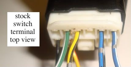
The ONLY mucking about with the connector on your ORIGINAL USDM OEM POWER MIRROR SWITCH CONNECTOR I want you to do is to ADD the wire in the right pin location from the JDM switch that isn't there. No cutting of the original wiring harness is necessary!
What does this mean? This means you are adding ONE WIRE to the USDM connector: BLU/YEL. It goes in pin slot #10 (in the corner). Now you plug it in to the JDM PFM switch. (Also, I KNOW that the USDM pin #2 is BLK/BLU when it is supposed to be BLK/YEL (as on JDM connector). DON'T concern yourself with this now. I don't know why it's like that, but I am SURE that it is wired to the fuse box properly.)
BLU/YEL runs to the....
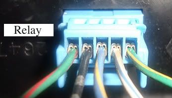
PFM RELAY
Yours looks like this:
____|----|____
[1][2][3][4][5]
[1]GRN/YEL
[2]WHT/BLU
[3]BLU/YEL
[4]BLK
[5]GRN/RED
- GRN/YEL and GRN/RED you extend to BOTH mirrors (ie., split the wires and extend them BOTH to EACH mirror)
- BLU/YEL arrives from the PFM switch
- BLK is extended to ground
- WHT/BLU gets +12V power .... SEE MY NOTE BELOW!
Since yours is a 6th Gen, and you do not have a blank spot on your under-dash fuse box to connect to (I've checked the diagrams), what you need to do is use a T-Taps connector and connect your WHT/BLU from the PFM relay to one of these two sources for power, both of which should be WHT/BLU wires, also: the Heater Control Panel or the Stereo Radio Tuner. These wires should pass through the under-dash fuse box somewhere ... they don't (shouldn't!) come OUT of the fuse box, they will be on a pass-through connector from the wiring harness that comes from behind the dash to the one that runs along the dashboard and behind the cluster (I THINK!!!!!!!! Not sure! But that's how 5th Gens are!)
THE MIRRORS
I actually think you have this pretty much sorted out. Except, in your diagram, you have GRN/ORG connecting with GRN/YEL on the mirrors (and vice versa). This is incorrect.
A few things to add. I have extra wiring with pins attached. Should the fatty soldered wire be replaced? I have my friends soldering kit, should soldering be done as thin as possible to avoid shorts? I am no expert in auto/soldering/wiring tech.
If I need a + and - source, is running wire to the battery my only option? Couldn't I find other sources like the kicker panel? Where are the stock mirrors getting their power from? Why can't I use the same + and - source from the stock mirrors for my new mirrors? My heads gonna explode!
This thread is posted on 3 different sites in hopes of finding answers. In total, this thread has over 213 views. I have not had much help, I am very grateful for all support and advice from anyone. Thx
PS. This link was pmed to me via ej8squad. It has some useful stuff IMO.
http://www.hondatech.co.uk/forum/vie...ghlight=#11137
PS. This link was pmed to me via ej8squad. It has some useful stuff IMO.
http://www.hondatech.co.uk/forum/vie...ghlight=#11137
GOOD LUCK!
Last edited by deschlong; Dec 30, 2009 at 02:40 PM. Reason: BLK wire from existing P/S door wiring not independent?
Thread Starter
Honda-Tech Member
Joined: May 2009
Posts: 220
Likes: 0
From: san jose
I am now 100% the mystery ORNANGE/white & BLACK wires lead to nothing. I physically checked the terminals on both sides just to make sure. I drew a diagram to better explain my findings. As for post #6, I don't have time to read your replies today. I will take a look at everything tomorrow. Got a lot of homework tonight.
White DS mirror terminal
[B]
[W][Y/B][Y/R][Y/W]
White DS mirror terminal
[B]
[W][Y/B][Y/R][Y/W]
Last edited by dgerej2; Jan 3, 2010 at 04:18 PM.
Trending Topics
Any progress?
I hope you can read Spanish. I found the Spanish EDM Helms with proper diagrams for 6th Gen Power Folding Mirrors. I extracted (+ removed the password) just the relevant bits for the mirrors and attached them as a PDF.
Looks like some of the wiring changed for 96-97 vs. 98-00. I included both diagrams so you can compare.
Looks like they also added heated mirrors for 99-00, but I didn't include that diagram as it is not relevant to what you're doing here.
Good luck!
OK, I just had a look at the 98-00 PFM wiring diagram I attached above. Interestingly, it looks like they did away with the relay beginning in these years, having changed the way the switch works. So, this means you should just need to consult the diagram from years 96-97 for your application.
Also, as I suspected, WHT/BLU for the folding relay is fused by No.47 - same one as for the Heater Control Panel and the Radio.
Also, as I suspected, WHT/BLU for the folding relay is fused by No.47 - same one as for the Heater Control Panel and the Radio.

Thread Starter
Honda-Tech Member
Joined: May 2009
Posts: 220
Likes: 0
From: san jose
Update: Progress slow due to Paramedic School!
Mirrors are wired 100%, JDM switch connected to OEM switch wires (these are the 7 remaining wire left over from the old switch).
I tested the mirrors and everythingthing worked perfectly the first time. Power adjust, FTW. A miracle!!! Now comes the hard part of making the relay work so the power folding feature is functional.

Thread Starter
Honda-Tech Member
Joined: May 2009
Posts: 220
Likes: 0
From: san jose
keh!? My power folding project is done! Just in case some one stumbles on this thread, the + source for the relay + wire is located just above the driver side fuse box by your feet. There are about 4 connections above the small fuses. You will need to attach a spade connector to your relay + wire in order to tap in. I will be doing a DIY on this project. It will be posted on clubcivic and ej8squad. Peace.
Honda-Tech Member
Joined: Apr 2010
Posts: 7
Likes: 0
From: La Puente626, killafornia
Sorry for bumping an old thread but i finally got my power folding mirrors to work and they are great. The only problem is i couldnt find the power source so I connected it directly to the battery for right now. My mirror switch is just like the ej8 squads diagram, straight row of wires in the back. Getting an alarm installed in a couple of days and having the peeps connect it to a power source and then i am taking pictures of it. look for my page in the next couple of weeks.

Honda-Tech Member
Joined: Aug 2003
Posts: 479
Likes: 0
From: NYC
Figured out it does have a built in relay. I used this diagram but I reversed the power folding wires which are painted red on "mirror 2". The mirrors fold/unfold with no problem, now I need to wire up the rest of the wires in order to adjust the mirrors.
Last edited by s2k drifter; Oct 28, 2015 at 05:56 PM.

Thread
Thread Starter
Forum
Replies
Last Post
fryman
Honda Civic / Del Sol (1992 - 2000)
22
Aug 7, 2012 11:58 AM
johnson_racing
Honda Civic / Del Sol (1992 - 2000)
1
Oct 30, 2009 02:27 PM
Dark_Ferio
Honda Civic / Del Sol (1992 - 2000)
4
Nov 28, 2005 06:31 AM