

How to test a relay?

Honda-Tech Member
Joined: Jan 2004
Posts: 10,629
Likes: 1
From: Further down the spiral, TX, usa
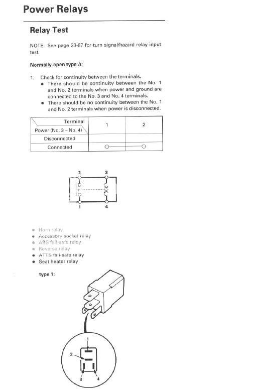
Basically it means that when power is flowing through the relay (from 3 to 4), then it should activate the other path inside the relay (from 1 to 2). Run power through 3 & 4 and then hook up 1 & 2 terminals to power and test them for flow with a multimeter.
Honda-Tech Member
Joined: Jan 2004
Posts: 10,629
Likes: 1
From: Further down the spiral, TX, usa
There should be options that say something like 2v, 20v, 200v, etc... 2v gives you readings like 1.435v, 20v setting gives you like 14.35v for example and 200 is like 143.5v.
Anyhow, use the 20v or whatever your mutimeter has that will include the power of the battery you use.
Anyhow, use the 20v or whatever your mutimeter has that will include the power of the battery you use.
Honda-Tech Member
Joined: Jun 2006
Posts: 448
Likes: 0
From: chicago, il, usa
don't know if you already figured it out, but the way i test them would be to set your meter to continuity, basically its an ohm reading of resistance. your meter will probably have a setting that beeps when there is continuity.
in this case with this particular relay, set your meter to continuity, test pins 1 and 2, and you should get no reading, basically an open circuit. now power the relay at pins 3 and 4, yes your 9v should work fine, and then test pins 1 and 2 again. you should now have continuity, if the relay works fine.
it's a lot easier than the two paragraphs i wrote
Trending Topics
Thread Starter
Honda-Tech Member
Joined: Oct 2003
Posts: 6,619
Likes: 0
From: Chicago

Thread
Thread Starter
Forum
Replies
Last Post
CrazyModGSR
Audio / Security / Video
5
Oct 29, 2004 11:32 AM