

VTEC Light issue

Thread Starter
Honda-Tech Member
Joined: Apr 2006
Posts: 187
Likes: 0
From: Lakenheath, UK
Tried hooking up a VTEC light in my coupe, and can't seem to get it to work. I took the time, and read the how-to that was posted on here a while back. It said to splice the LED power wire to the GREEN wire with the YELLOW stripe. I did that, and it didn't work. (yes the negative side of the LED is grounded) Checked under the hood to the wire connecting to the VTEC solenoid, and it was green w/ yellow stripe. Whipped out the Multimeter and shot the wire, it was only kicking back 3v. Shot it @ about a sustained 6000 rpm hold, while the engine was warm, heard VTEC engage and sustain, so I know everything else in the system is working properly. The write-up said that the light is powered off of a 12v line, so I'm at a loss. I am starting to think that the ECU the guy did his write-up on was a P30 or a P72. I have a D16Z6 w/ a P28. Could I be looking at the wrong wire? Been hunting for a schematic all week of the wiring diagram of a P28, and this is the best that I could come up with.
'92-'95 D16z6 ECU Pinout
A1 Injector #1
A2 Injector #4
A3 Injector #2
A4 VTEC Solenoid (AKA Spool Solenoid Valve)
A5 Injector #3
A6 O2 Heater Control
A7 Fuel Pump Relay (Connected with A8)
A8 Fuel Pump Relay (Connected with A7)
A9 EACV (Electronic Air Control Valve) (AKA IACV)
A10
A11
A12 Radiator Fan Relay/Coolant Temp Switch
A13 Check Engine Light
A14
A15 A/C Compressor Clutch Relay
A16 Alternator (GC)
A17 (A/T) Lock-Up Control Solenoid Valve B
A18
A19 (A/T) Lock-Up Control Solenoid Valve A
A20 Purge Cut-Off Solenoid Valve
A21 Ignition Control Module #1
A22 Ignition Control Module #2
A23 Ground #1 (Main Relay)
A24 Ground #2 (Main Relay)
A25 Ignition Power #1 (Battery)
A26 Logic Ground #1
-
B1 Ignition Power #2
B2 Logic Ground #2
B3 (A/T) Shift Position Indicator (D3 Position)
B4 (A/T) Shift Position Indicator (D4 Position)
B5 A/C Switch
B6
B7 (M/T) Clutch Switch /(A/T) Shift Position Indicator (Park and Neutral Position)
B8 Power Steering Oil Pressure Switch
B9 Starter Switch Signal
B10 Vehicle Speed Sensor
B11 CYL Sensor Power (#1 Cylinder Position)
B12 CYL Sensor Ground (#1 Cylinder Position)
B13 Top Dead Center (TDC) Position Sensor Power
B14 Top Dead Center (TDC) Position Sensor Ground
B15 Crank Sensor Power
B16 Crank Sensor Ground
-
D1 Diagnostic Trouble Codes (DTC) Memory Voltage
D2 Brake Switch
D3
D4 Service Check Connector
D5
D6 VTEC Oil Pressure Switch (AKA Valve Timing Oil Pressure Switch)
D7 Data Link Connector
D8
D9 Alternator (GF)
D10 Electric Load Detector (AKA ELD)
D11 Throttle Position Sensor (Signal)
D12
D13 Coolant Temperature Sensor (AKA ECT and TW)
D14 O2 Signal Wire
D15 Intake Air Temperature Sensor (AKA TA Sensor and IAT)
D16
D17 MAP
D18 Shift-Up Indicator (M/T), Interlock Control Unit (A/T)
D19 MAP Sensor Voltage
D20 Throttle Position Sensor Voltage
D21 MAP Sensor Ground
D22 Ground (IAT, ECT, TPS, O2 Sensor)
Even with this, I can't find a pictoral layout to decipher which pins are which, and the plugs themselves are not marked. Any help to shed light on this would be nice, I just want a little do-dad in my car so my friends will get a good laugh when I go into VTEC. Thanx in advance for the help folks.
Honda-Tech Member
Joined: Oct 2002
Posts: 5,152
Likes: 24
From: chicago burbs, Il, USA
P28, P30, P72, P61, P06(with VTEC control added) it doesn't matter the VTEC output is 12V active, 0V inactive for all of them.
picture of the terminals of the OBD1 ECU.
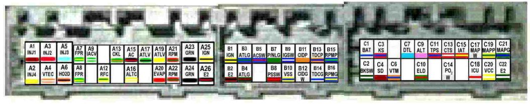
the VTEC solinoid has to have 12V to actuate the solinoid, if it's getting 3V it will not open and you will not have the high cam lobe in operation.
did you use a 12V LED? if you used a normal LED that's designed for 3-6V you popped the LED for sure, and may have damaged the driver for the VTEC solinoid in the ECU.
It's unlikely that it's damaged, they have an internal protection, but I've seen it happen.
picture of the terminals of the OBD1 ECU.
the VTEC solinoid has to have 12V to actuate the solinoid, if it's getting 3V it will not open and you will not have the high cam lobe in operation.
did you use a 12V LED? if you used a normal LED that's designed for 3-6V you popped the LED for sure, and may have damaged the driver for the VTEC solinoid in the ECU.
It's unlikely that it's damaged, they have an internal protection, but I've seen it happen.
Thread Starter
Honda-Tech Member
Joined: Apr 2006
Posts: 187
Likes: 0
From: Lakenheath, UK
Alright, I got it to work. You have to go off of A4 (orange w/ white stripe). I was going off of D6, and wasn't getting a reading. Also, to test it, the engine has to be under load. It won't go VTEC sitting still. One of my friends swore up and down that we could sit there and rev it and VTEC would engage. I finally talked him into going around the block ONE time, and voila, lit up like day. Thanx for the help guys. For people referencing this issue later, here are fast facts.
-Go off of plug A4 (VTEC solenoid) orange wire w/ white stripe.
-12V LED only
-positive(+) side to VTEC solenoid line
-negative(-) side to ground
-to test, engine must be under rolling load to engage VTEC.
-Go off of plug A4 (VTEC solenoid) orange wire w/ white stripe.
-12V LED only
-positive(+) side to VTEC solenoid line
-negative(-) side to ground
-to test, engine must be under rolling load to engage VTEC.

Thread
Thread Starter
Forum
Replies
Last Post
Jizzmaster Zero
Honda Civic / Del Sol (1992 - 2000)
5
Sep 29, 2005 03:43 PM