When you click on links to various merchants on this site and make a purchase, this can result in this site earning a commission. Affiliate programs and affiliations include, but are not limited to, the eBay Partner Network.
I will keep the switched ground (-) at A17, and then look to pick up 12v (+) signal YEL/BLK wire. I have heard there is a "dead end" connector on the driver side of the engine bay? I will look for this.
Then I need to figure out if I have the solenoid for '94 & '95, or the '96 - '01, since the plugs changed polarity :-(
Ok so obd1 p72 ecu, pink/blue goes to a17 and yelllow/black goes to 12v constant. Just making sure before I hook it up. And I could potentially find a 12v dead hookup on the driver side fire wall. If any one has a picture of this hookup point for reference that would be great. Also I just realized that the top piece on the IAB is cracked and broken, reference part number 5 in the diagram for the IAB for 94-95. Can I just hook up a hose to it and plug the other end?
Ok so obd1 p72 ecu, pink/blue goes to a17 and yelllow/black goes to 12v constant. Just making sure before I hook it up. And I could potentially find a 12v dead hookup on the driver side fire wall. If any one has a picture of this hookup point for reference that would be great. Also I just realized that the top piece on the IAB is cracked and broken, reference part number 5 in the diagram for the IAB for 94-95. Can I just hook up a hose to it and plug the other end?
Looks like part #5 is a $13 filter, you could just replace it...
Ok so obd1 p72 ecu, pink/blue goes to a17 and yelllow/black goes to 12v constant. Just making sure before I hook it up. And I could potentially find a 12v dead hookup on the driver side fire wall. If any one has a picture of this hookup point for reference that would be great. Also I just realized that the top piece on the IAB is cracked and broken, reference part number 5 in the diagram for the IAB for 94-95. Can I just hook up a hose to it and plug the other end?
Maybe I'm thinking too simply but why not run the wire to A17, then the other side to a switched 12V source (I've often just tapped the EVAP plug since its right there. Do a test, start at idle to see if they are closed and then rev it to the switched RPM) and see if it operates as normal. If not just reverse the wires in the connector and see if it does it then.
Maybe I'm thinking too simply but why not run the wire to A17, then the other side to a switched 12V source (I've often just tapped the EVAP plug since its right there. Do a test, start at idle to see if they are closed and then rev it to the switched RPM) and see if it operates as normal. If not just reverse the wires in the connector and see if it does it then.
That is funny, I was thinking of the YEL/BLK 12v (+) from Evap as well.
You are not thinking too simply, it is just that my head and intake are off right now, and while I am waiting for a ball hone I thought I would clean up the wiring under the intake. https://honda-tech.com/forums/honda-...ident-3276594/
So I was trying to get it all correct now, w/o the benefit of being able to troubleshoot the IAB w/ engine running.
I just personally didn't want to eliminate the evap completely. But if I can just tap into the wire and still have the evap than that sounds like a way that would work for me. If I'm not understanding this correctly than let me know. Pink/blue goes to a17 and yellow/black can be tapped into evap wire for simple hook up? I will try this method like you said and see if it works.
I just personally didn't want to eliminate the evap completely. But if I can just tap into the wire and still have the evap than that sounds like a way that would work for me. If I'm not understanding this correctly than let me know. Pink/blue goes to a17 and yellow/black can be tapped into evap wire for simple hook up? I will try this method like you said and see if it works.
I think that is correct, and that is the way I plan to do it.
Hopefully my last question (for a while); If I have been running around w/o my IAB working, do you think I will feel a noticeable difference when it works?
With a cut-off at 5750 RPM, I think I spend 85% of time below that RPM, so the engine has been using the short runners all that time...
I'm
jj
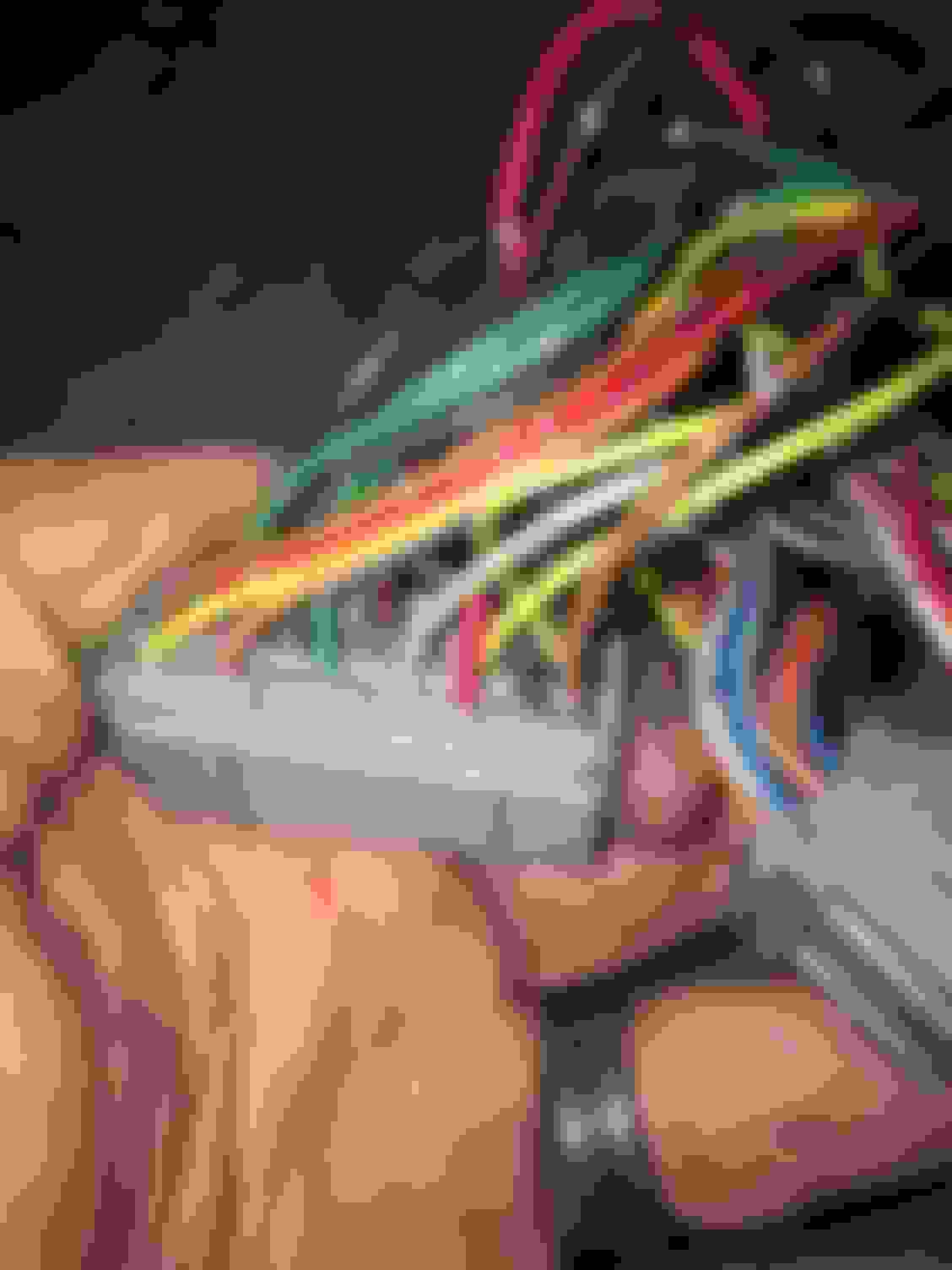
okay so I hope you guys can see these pictures...
so above is the main plug for the ecu, and so if you look at the red wire on the far right that would be the Pcs (evap purge control solenoid valve) in the manual as for the other two wires that are for the evap are not on the harness. Is this normal? Also since the red wire for the evap is the wire I'm connecting the IAB to. will the IAB operate the same as the evap and open up after the engine has warmed up and will it shut when the evap decides to shut Itself. I guess what I'm wondering is will the IAB function the way it's intended hooked up to the same wire controlling the evap? I know this seems to be a drawn out thread on this issue, but I am very new to this type of thing. Any info is greatly appreciated.
Hopefully my last question (for a while); If I have been running around w/o my IAB working, do you think I will feel a noticeable difference when it works?
With a cut-off at 5750 RPM, I think I spend 85% of time below that RPM, so the engine has been using the short runners all that time...
From my understanding your torque curve will have a flat spot.
The GSR intake manifold has two set of runners, short and long. Essentially you get three stages from the intake and head.
Below 4400rpm - Long runners, no VTEC
4400-5750rpm - long runners, VTEC
Above 5750rpm - short runners, VTEC
If you don't connect the IABs you'll end up without the short runners. Creating a power curve similar to a B16/Type R.
I'm a bit interested in this as well. I've got a 1992 VX and a 1995 B18C1 and OBD 1 P72 ECU.
What I'm not understanding is the need to find a connection for the YEL/BLK wire.
I thought that repinning A20 to A17 was all that was required. The YEL/BLK would be taken care of with the C125 and C127.
Since power (YEL/BLK) is deliver through the cabin harness at C301 to the engine harness at C125, and assuming a GSR engine harness, the YEL/BLK should already be there. Leaving only the A20/A17 repinning of the ECU.
To add the EVAP control solenoid you would have to run a wire from a YEL/BLK source to the right side of the GSR engine harness as well as a wire from A20 to the harness.
Is this not correct (for OBD1 Civic to OBD1 B18C1)?
My 94 integra is the Ls and I'm useing the Ls harness for my B18C gsr motor. Both motor and harness are obd1. As I understand it I should pin pink/blue into a17 and the other wire would get tapped into the evap wire going to a20. But with that hook up my question was will the IAB still function the way it is intended tapped into the evap?
My 94 integra is the Ls and I'm useing the Ls harness for my B18C gsr motor. Both motor and harness are obd1. As I understand it I should pin pink/blue into a17 and the other wire would get tapped into the evap wire going to a20. But with that hook up my question was will the IAB still function the way it is intended tapped into the evap?
You aren't going to have a PNK/BLU wire. That's exclusive to the GSR engine harness.
You'll move the RED A20 wire on the ECU to the A17 slot (it's open on you ECU). If you want an evap solenoid you'll need to run a wire from A20 and another wire from a YEL/BLK source.
For the IAB the YEL/BLK is the same YEL/BLK to the evap solenoid. Look at the second picture in my post above. You'll see the for the LS/RS harness the evap has a deadicated YEL/BLK. By moving A20 to A17 on the ECU you creating a complete IAB connector from the evap connector.
I'm
jj
okay so I hope you guys can see these pictures...
so above is the main plug for the ecu, and so if you look at the red wire on the far right that would be the Pcs (evap purge control solenoid valve) in the manual as for the other two wires that are for the evap are not on the harness. Is this normal? Also since the red wire for the evap is the wire I'm connecting the IAB to. will the IAB operate the same as the evap and open up after the engine has warmed up and will it shut when the evap decides to shut Itself. I guess what I'm wondering is will the IAB function the way it's intended hooked up to the same wire controlling the evap? I know this seems to be a drawn out thread on this issue, but I am very new to this type of thing. Any info is greatly appreciated.
I can see the pictures.
A few thoughts after reading your post...
First, disregard the FSM page showing a drawing of the connector you have posted above, it is for OBD2. The connector you are holding in your hand is OBD1. This is the same trap I fell into earlier in this thread.
The OBD1 connector is like this - the sucky thing is the '94 Integra manual does not label the pins like the OBD2 manual you included:
Next, what ECU/ECM do you have in your vehicle? You know you cannot use the LS computer to run your B18C1, right? Before you worry about any of these other details, make sure you have the appropriate ECU/ECM in place.
I believe you said you want to keep your Evap Purge, yes? Then just leave the red wire in A20. That and your YEL/BLK from the PGM-FI main relay will power your evap. A20 should provide switched ground (-) once the engine coolant temp is > 163 F. Make sense?
You need to run a wire from A17 to your IAB solenoid for switched ground (-). A17 should supply ground (-) when the engine is tarted all the way up to 5750 RPM, at which point it will disco the (-) and the solenoid will deactivate. So no, the A17 pin will not behave the same as the A20 pin, which is what I think you were trying to ask.
I do not know if the A connector has metal terminals present in the empty spaces (A17). If yes, great - get it out and crimp your wire for A17 in there and then run it out to your IAB. Depending on what year IAB solenoid you have, wire it to the correct side of the connector. The other terminal will need to get 12v (+) signal. I am going to go with that YEL/BLK that is powering Evap Purge as has been suggested due to its proximity.
If your ECU/ECM connector A does not have a terminal in A17, you will need to find one. I think @HondaPartsHero sells many electrical connector parts. I would start with a PM to him/her.
Does that help?
Last edited by 94 Civic Si; Jan 28, 2017 at 01:51 PM.
From my understanding your torque curve will have a flat spot.
The GSR intake manifold has two set of runners, short and long. Essentially you get three stages from the intake and head.
Below 4400rpm - Long runners, no VTEC
4400-5750rpm - long runners, VTEC
Above 5750rpm - short runners, VTEC
If you don't connect the IABs you'll end up without the short runners. Creating a power curve similar to a B16/Type R.
That's my understanding at least.
eH.
If my solenoid is always off b/c it is connected to switched ground (-) and ground (-) on the engine block, I think I have been using the short runners the entire time!
I'm a bit interested in this as well. I've got a 1992 VX and a 1995 B18C1 and OBD 1 P72 ECU.
What I'm not understanding is the need to find a connection for the YEL/BLK wire.
I thought that repinning A20 to A17 was all that was required. The YEL/BLK would be taken care of with the C125 and C127.
Since power (YEL/BLK) is deliver through the cabin harness at C301 to the engine harness at C125, and assuming a GSR engine harness, the YEL/BLK should already be there. Leaving only the A20/A17 repinning of the ECU.
To add the EVAP control solenoid you would have to run a wire from a YEL/BLK source to the right side of the GSR engine harness as well as a wire from A20 to the harness.
Is this not correct (for OBD1 Civic to OBD1 B18C1)?
eH.
If you have the GSR engine harness, then I bet you are correct, you have connectors for IAB and purge. The starter of this thread states they have a JDM B18C(5?), so no IAB would have come with that, eh? As for me, The shop that swapped my B18C1 put in from a '96 (OBD2) and did not wire the IAB correctly for me. They did run a wire from A17 for me, so I will use that, but I do need 12v (+) to complete the circuit, thus my need to tap into that YEL/BLK wire...
Last edited by 94 Civic Si; Dec 5, 2016 at 04:55 PM.
You aren't going to have a PNK/BLU wire. That's exclusive to the GSR engine harness.
You'll move the RED A20 wire on the ECU to the A17 slot (it's open on you ECU). If you want an evap solenoid you'll need to run a wire from A20 and another wire from a YEL/BLK source.
For the IAB the YEL/BLK is the same YEL/BLK to the evap solenoid. Look at the second picture in my post above. You'll see the for the LS/RS harness the evap has a deadicated YEL/BLK. By moving A20 to A17 on the ECU you creating a complete IAB connector from the evap connector.
At least that's what I'm seeing.
eH.
Or if he wants to keep the Evap Purge, leave the correct color wire in A20 and run wire from A17 to IAB, eh?
I did find some PNK/BLU wire and ordered it. It may be overkill, but why not have the correct color stuff if possible?
If you have the GSR engine harness, then I bet you are correct, you have connectors for IAB and purge. The starter of this thread states they have a JDM B18C(5?), so no IAB would have come with that, eh? As for me, THe shop that swapped my B18C1 put in from a '96 (OBD2) and did not correct IAB correctly for me. They did run a wire from A17 for me, so I will use that, but I do need 12v (+) to complete the circuit, thus my need to tap into that YEL/BLK wire...
If OP had a GSR B18C he would have IABs and need to wire them if using an LS engine harness.
If OP had a Type R B18C he doesn't have IABs.
The difference between the two is usually with the head, in this case we're talking about the intake manifold.
Without more information, or a picture, we don't know which B18C engine OP has.