

DIY shock dyno

Thread Starter
Honda-Tech Member
Joined: Jun 2004
Posts: 1,160
Likes: 1
From: Bay Area, CA, usa
Tired of paying $20+ per shock just to get a lousy 6 datapoint dyno "plot"? Want to make sure your shocks are matched, or even blown? Why not build one yourself and save?!?!??!
Here's a ghetto dyno I built using a few pieces of unistrut, a load cell I got off ebay, a potentiometer, and a few machined bits to make it all fit together:
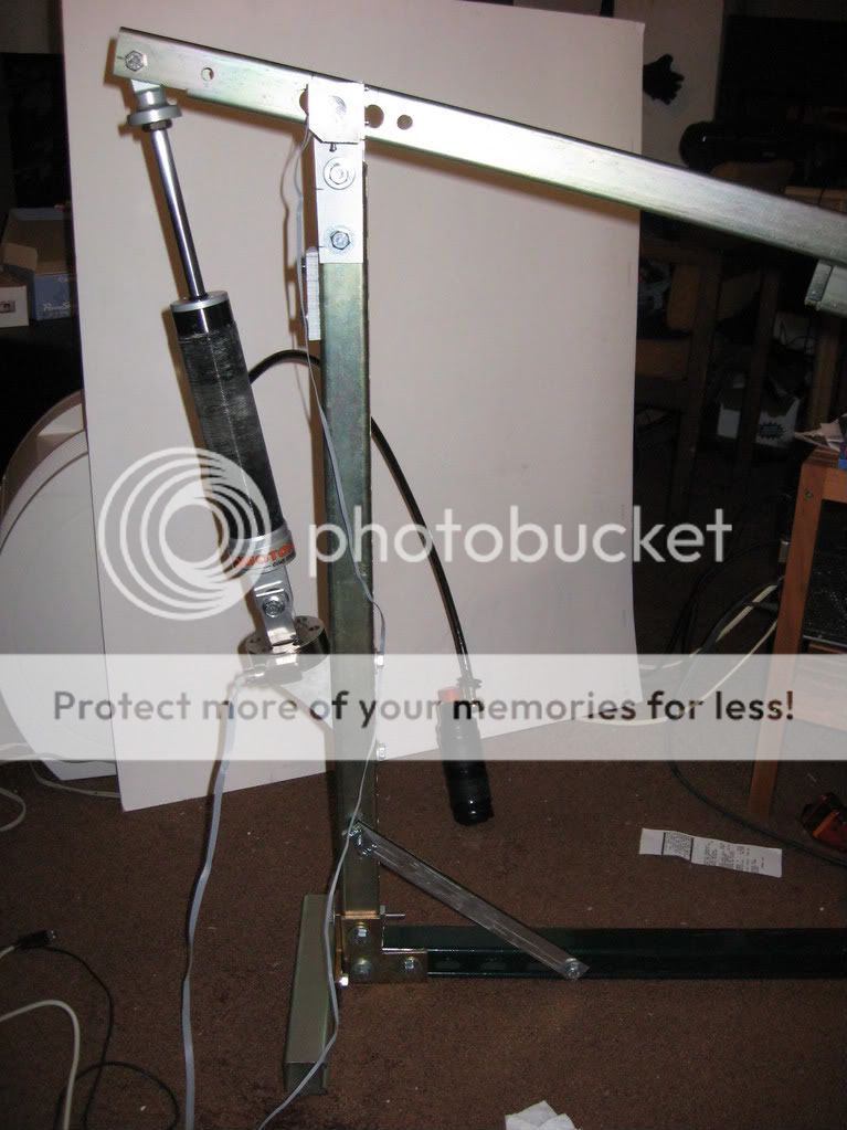
You can see that I have some random no-name shock attached to it right now. It only claims to be "2 way adjustable", which isn't even as good as those 24+ way adjustable JDM shocks. I'm not sure what that thing attached to it is. Maybe NOS or whatever. LOL Fricking thing has eyelets on both ends of it, so I'm not sure how I'm going to attach it to my car.
Next up is the measurement circuitry. Just two IC's and a USB DAQ card, for about $160 or so. Oh yeah, and also a laptop running Labview and MATLAB.

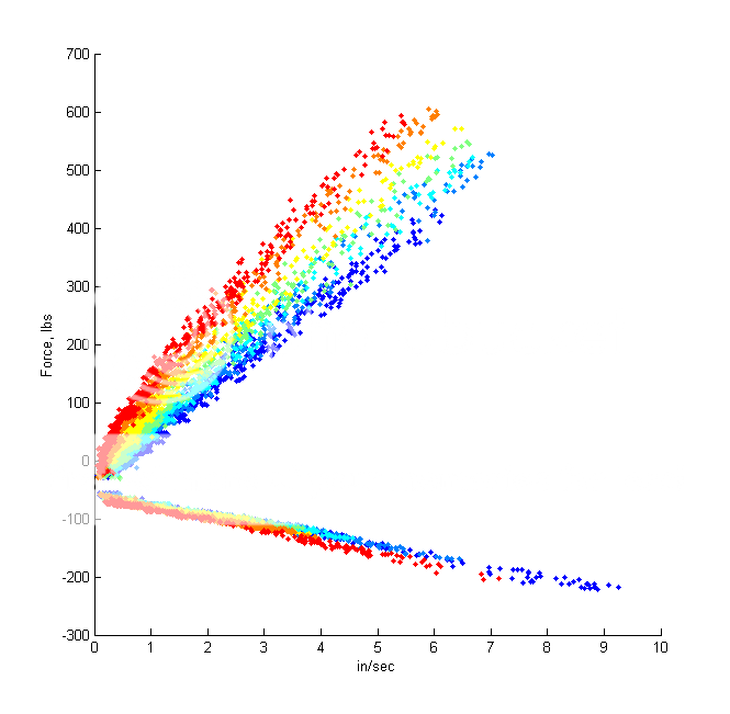
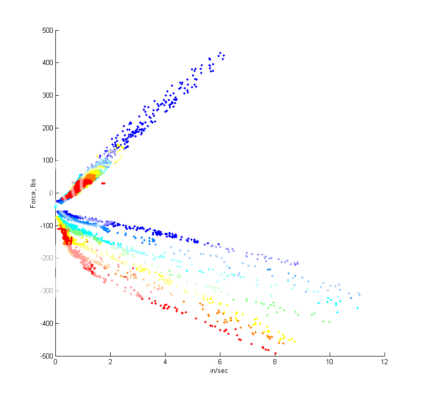
Here's a dyno plot of that no-name shock. They lied in their advertising, coz the rebound **** actually clicked 6 times. Which means the shock is "6 way adjustable". Sheesh. Looks like it has pretty linear valving. If you like that kind of thing.
Next up is a Koni 8211 twin tube. It has twice the tubes, so it must be twice as good.
Compression adjust:
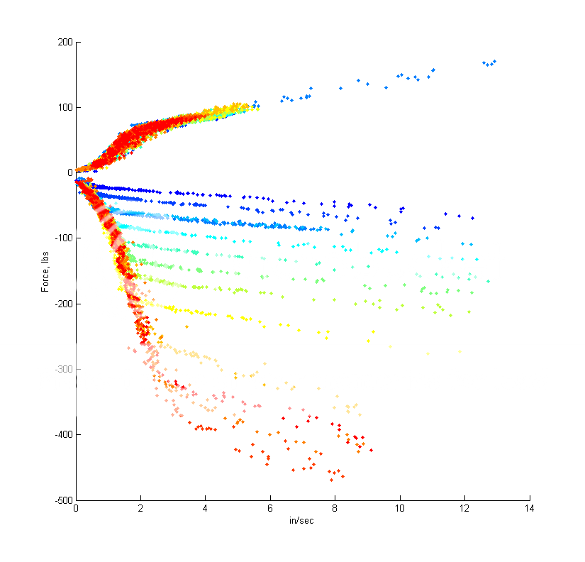
Talk about a digressive blow off... I only run it around 2-3 clicks from full soft, so if 3 in/sec is the magic knee number, then maybe it is turning over too early for me. I dunno.
Next up is rebound sweep:
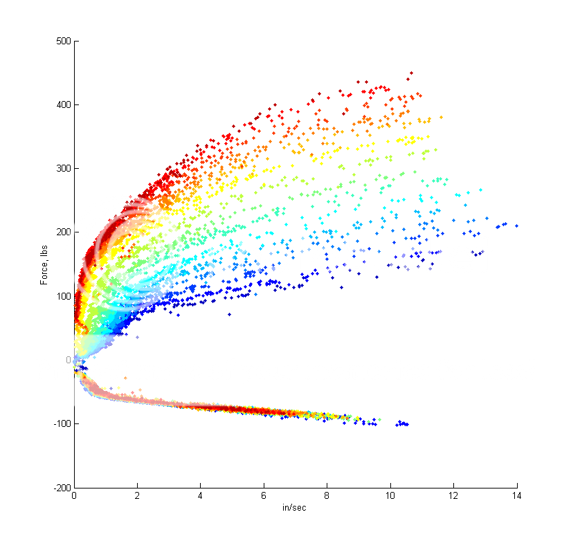
A bit more rounded knee. I run this at around the middle setting, but I'm still not sure if it is turning over at the right point. Oh well.
I also have a Koni yellow, but compared to these other two shocks, it looks really thin and puny. There's still a lot more to do with data analysis and finding out the behavior of these shocks under different conditions, e.g. turn-around point, reaction to acceleration and jerk, etc.
Also, doing a full sweep gives you a pretty good workout.
Here's a ghetto dyno I built using a few pieces of unistrut, a load cell I got off ebay, a potentiometer, and a few machined bits to make it all fit together:
You can see that I have some random no-name shock attached to it right now. It only claims to be "2 way adjustable", which isn't even as good as those 24+ way adjustable JDM shocks. I'm not sure what that thing attached to it is. Maybe NOS or whatever. LOL Fricking thing has eyelets on both ends of it, so I'm not sure how I'm going to attach it to my car.
Next up is the measurement circuitry. Just two IC's and a USB DAQ card, for about $160 or so. Oh yeah, and also a laptop running Labview and MATLAB.
Here's a dyno plot of that no-name shock. They lied in their advertising, coz the rebound **** actually clicked 6 times. Which means the shock is "6 way adjustable". Sheesh. Looks like it has pretty linear valving. If you like that kind of thing.
Next up is a Koni 8211 twin tube. It has twice the tubes, so it must be twice as good.
Compression adjust:
Talk about a digressive blow off... I only run it around 2-3 clicks from full soft, so if 3 in/sec is the magic knee number, then maybe it is turning over too early for me. I dunno.
Next up is rebound sweep:
A bit more rounded knee. I run this at around the middle setting, but I'm still not sure if it is turning over at the right point. Oh well.
I also have a Koni yellow, but compared to these other two shocks, it looks really thin and puny. There's still a lot more to do with data analysis and finding out the behavior of these shocks under different conditions, e.g. turn-around point, reaction to acceleration and jerk, etc.
Also, doing a full sweep gives you a pretty good workout.


Thread Starter
Honda-Tech Member
Joined: Jun 2004
Posts: 1,160
Likes: 1
From: Bay Area, CA, usa
Update:
Since a couple people asked, here's some more info about how to make it. The most chalenging part is to make the pivot for the thing.
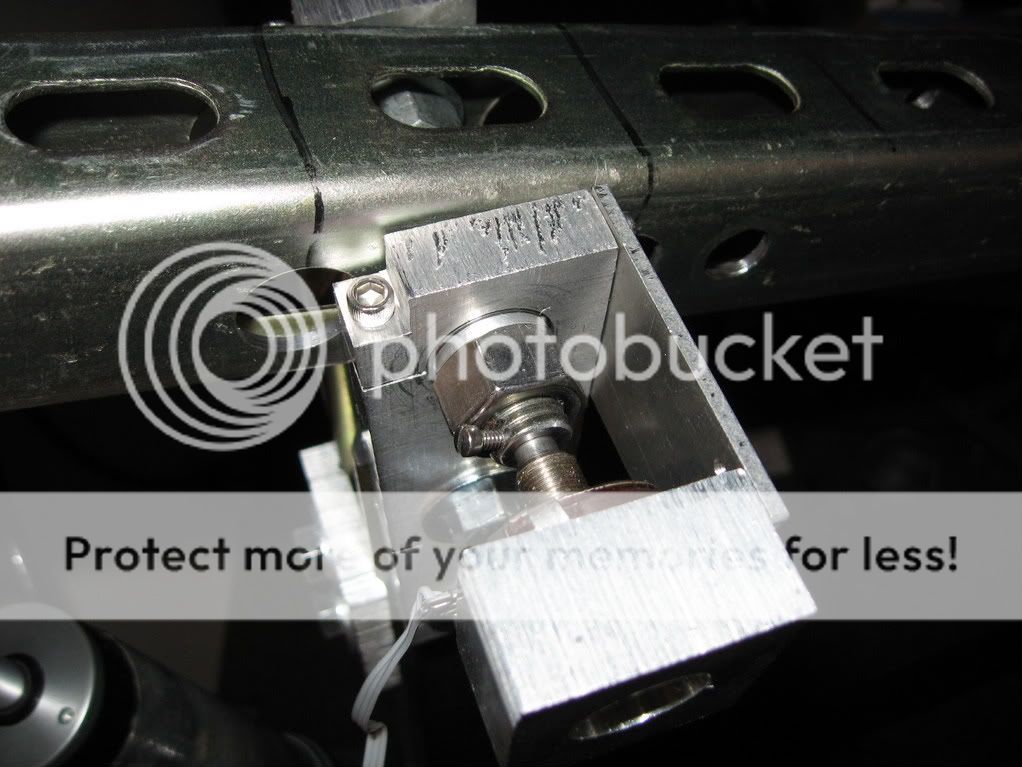
I'm sure you could make something better than this, but here's what I did. I had two worn spherical bearings laying around, so I cut a slit in the outer case with the bandsaw. The bearing is embedded inside that aluminum piece, and the allen head screw squeezes down on the bearing to take out some play. Ideally, you would use a sealed ball bearing, like a leftover pilot bearing from your flywheel or whatever. I only had one of these, but I need one on each side.
there's basically a threaded rod that runs thru the unistrut, with nuts that clamp it down. On the side with the potentiometer, I drilled a 1/4" hole in the threaded rod to stick the shaft of the pot into. The horizontal bar and the threaded rod move as one piece and the vertical unistrut and pot body stay fixed, so that's how to do rotation sensing. Right now, there is still a little bit of play in this joint, so it throws off the dyno data near the transition points. Also, this whole unistrut assembly is a little bit flexy (expecially when you are pumping furiously and applying 600 lbs on it, so it needs a little beefing up.
I leave the data acquisition and analysis up to you. I already have Labview, but I think that USB DAQ comes with some kind of data acquisition program as well. For the data analysis, I just plotted F vs V, and omitted some data around the turn around points for now. Later, they will be useful. If you don't have MATLAB, you can use Octave, a free open-source knockoff.
Modified by beanbag at 12:34 PM 6/18/2008
Since a couple people asked, here's some more info about how to make it. The most chalenging part is to make the pivot for the thing.
I'm sure you could make something better than this, but here's what I did. I had two worn spherical bearings laying around, so I cut a slit in the outer case with the bandsaw. The bearing is embedded inside that aluminum piece, and the allen head screw squeezes down on the bearing to take out some play. Ideally, you would use a sealed ball bearing, like a leftover pilot bearing from your flywheel or whatever. I only had one of these, but I need one on each side.
there's basically a threaded rod that runs thru the unistrut, with nuts that clamp it down. On the side with the potentiometer, I drilled a 1/4" hole in the threaded rod to stick the shaft of the pot into. The horizontal bar and the threaded rod move as one piece and the vertical unistrut and pot body stay fixed, so that's how to do rotation sensing. Right now, there is still a little bit of play in this joint, so it throws off the dyno data near the transition points. Also, this whole unistrut assembly is a little bit flexy (expecially when you are pumping furiously and applying 600 lbs on it, so it needs a little beefing up.
I leave the data acquisition and analysis up to you. I already have Labview, but I think that USB DAQ comes with some kind of data acquisition program as well. For the data analysis, I just plotted F vs V, and omitted some data around the turn around points for now. Later, they will be useful. If you don't have MATLAB, you can use Octave, a free open-source knockoff.
Modified by beanbag at 12:34 PM 6/18/2008
Trending Topics

Honda-Tech Member
Joined: Apr 2005
Posts: 220
Likes: 0
From: Pittsburgh, PA
That's pretty interesting machine you got there. Kudos for the ingenuity. I agree on those cheap M-word stuff. What kind of respectable company doesn't fit like OEM anyway...lol.
On a serious note.......it never ceases to amaze me just how many people will look OBJECTIVE data like that, and completely miss what it teaches you....obviously because an ad in ImportTuner is far more relevant, right?
On a serious note.......it never ceases to amaze me just how many people will look OBJECTIVE data like that, and completely miss what it teaches you....obviously because an ad in ImportTuner is far more relevant, right?
Honda-Tech Member
Joined: Jul 2001
Posts: 721
Likes: 0
From: atlanta, ga, usa
Sweet set up. It took me a minute to figure out that your graphs are opposite of conventional force/distance graphs. The negative range of the force axis is actually compressive resistance and the positive is rebound resistance.
Could you do an indexed sweep of the "no-names" for the compressive stroke?
Could you do an indexed sweep of the "no-names" for the compressive stroke?
Honda-Tech Member
Joined: Oct 2003
Posts: 6,619
Likes: 0
From: Chicago
<TABLE WIDTH="90%" CELLSPACING=0 CELLPADDING=0 ALIGN=CENTER><TR><TD>Quote, originally posted by glagola1 »</TD></TR><TR><TD CLASS="quote">Yeah, I've seen it both ways too but the negative denomination (wether it be up or down from the 0 on the Y axis) is always for rebound. </TD></TR></TABLE>
Doesn't seem to be the case.
Suspension forum Shock Dyno thread: https://honda-tech.com/zerothread/1104049
Doesn't seem to be the case.
Suspension forum Shock Dyno thread: https://honda-tech.com/zerothread/1104049
Honda-Tech Member
Joined: Oct 2004
Posts: 2,088
Likes: 0
From: All over ATL
Holy cow you can definitely see the difference between the settings on the Motons. That is totally awesome on the DIY machine too. I guess that's why Motons cost about as much as a car.  I wonder what Penskes look like.
I wonder what Penskes look like.

Senior Member
Joined: Jun 2004
Posts: 10,399
Likes: 3
From: Chicagoland, IL
That's a pretty neat setup. I was slightly surprised to see how good the data was (though, not as pretty as the stuff you'll see on a "pro" shock dyno, but who cares.)
Is that hand-powered? I couldn't tell for sure but I'm assuming it's powered by your arm at the end of the top arm.
Is there any chance you were able to limit the displacement area that you take the measurement, or is it possible that a given data point could be taken anywhere on the stroke of the shock?
-Chris
Honda-Tech Member
Joined: Jul 2001
Posts: 721
Likes: 0
From: atlanta, ga, usa
Also, it seems like the data would be skewed on some sort of curve based on the fact that the lever that pushes on the shock goes through different stages of mechanical advantage as it goes through its arc. I suppose there might be a way to resolve this with those computer thingies...
Senior Member
Joined: Jun 2004
Posts: 10,399
Likes: 3
From: Chicagoland, IL
<TABLE WIDTH="90%" CELLSPACING=0 CELLPADDING=0 ALIGN=CENTER><TR><TD>Quote, originally posted by glagola1 »</TD></TR><TR><TD CLASS="quote">Also, it seems like the data would be skewed on some sort of curve based on the fact that the lever that pushes on the shock goes through different stages of mechanical advantage as it goes through its arc. I suppose there might be a way to resolve this with those computer thingies...</TD></TR></TABLE>
nope, the pressure sensors are on the damper itself, not the lever, so it looks good to me. Regardless of mechanical advantage, the sensor will always read the force exerted by the damper.
nope, the pressure sensors are on the damper itself, not the lever, so it looks good to me. Regardless of mechanical advantage, the sensor will always read the force exerted by the damper.
Honda-Tech Member
Joined: Jul 2001
Posts: 721
Likes: 0
From: atlanta, ga, usa
There are two senors that make up the x and y of the plot. The force is a constant as you stated but the velocity is what is in question here. The way the device is set up does not account for the fact that the piston moves different distances relative to where the arm is in it's arced stroke. So, the potentiometer reads distance in terms of degrees of revolution vs the actual linear stroke of the shock piston.
A better set up would to be have a linear potentiometer attached along the piston.
Still, it's a badass rig and the results are repeatable. I just wouldn't trust the values as absolute but a good comparison shock to shock could be made.
A better set up would to be have a linear potentiometer attached along the piston.
Still, it's a badass rig and the results are repeatable. I just wouldn't trust the values as absolute but a good comparison shock to shock could be made.
Senior Member
Joined: Jun 2004
Posts: 10,399
Likes: 3
From: Chicagoland, IL
<TABLE WIDTH="90%" CELLSPACING=0 CELLPADDING=0 ALIGN=CENTER><TR><TD>Quote, originally posted by glagola1 »</TD></TR><TR><TD CLASS="quote">A better set up would to be have a linear potentiometer attached along the piston.</TD></TR></TABLE>
Ah ha, I see it now. I missed your point the first time.
Ah ha, I see it now. I missed your point the first time.
