

can somone PLEASE confirm which one of these two is a p28 pinout\diagrem?
 09-25-2006, 10:54 AM
#1
Honda-Tech Member
Thread Starter
hello
hello everyone,
can somone please tell me once and 4 all which diagram is for a p28?
this:

OBD1
A1-INJ1 INJ1 Brown, Battery Voltage with KOEO
A2-INJ4 INJ4 Yellow, Battery Voltage with KOEO
A3-INJ2 INJ2 Red, Battery Voltage with KOEO
A4-VTS VTEC solenoid GRN/YEL, N/a
A5-INJ3 INJ3 Blue, Battery Voltage with KOEO
A6-PO2SHTC O2 sensor (heating element) Org/Wht, Battery Voltage with KOEO
A7-FLR1 fuel pump Grn/BLK, Battery Voltage with KOEO
A8-empty A7 and A8 have the same circurt, so they can be the same
A9-IACV IAC valve Blk/Blu, About 10v KOEO on Warm engine
A10-empty
A11- This is EGR Control Solenoid Valve (if the ECU has) Red, N/A
A12-FANC engine coolant temp switch Blu/red, N/A
A13-MIL MIL (check engine light) Blu/wht, N/A
A14-empty
A15-ACC (a/c compressor clutch) Red/Blu, N/A
A16-ALT C alternator Wht/Grn, N/A
A17-IAB IAB Solenoid Pink, N/A
A18- Org/Red, Transmission Control Module (A/T), N/A
A19- White, Intake control solenoid, Battery Voltage with KOEO
A20-PCS EVAP purge control solenoid Red/Grn, N/a
A21-ICM ICM Yel/Grn, Ignition Control Module (ICM) Output signal, About 10V KOEO
A22- *per Sander* Ignitor same as A21
A23-PG1 ground Black, Power ground, less than 1V
A24-PG2 ground same as A23
A25-IGP2 to main relay and to gound for o Yel/blk, Battery positive from Main relay, Battery Voltage with KOEO
A26-LG1 gound Blk/red, less than 1V
B1-IGP2 to pin A25 Yel/Blk, Battery positive from Main relay, Battery Voltage with KOEO
B2-LG2 ground to shields for CYP & TDC Brown/Blk, Less than 1V
B3- Orange, upshift/downshift comparative input, N/A
B4- Pink, upshift/downshift comparative input, N/A
B5-ACS a/c switch Blu/Blk, A/c input, About 5V with KOEO & A/C off; less than 1V KOER with A/C & blower on
B6-empty
B7- Light green, Park/Neutral switch (A/T), Less than 1V in Park or Neutral with KOEO; 5V in Park or neutral with KOER; Battery voltage in all other positions
B8-PSPSW PSP switch Red/Green, Power steering oil pressure switch, 0V KOEO; Battery Voltage KOER While slowly turning steering wheel
B9-STARTER SIGNAL starter signal Blue/red, Battery Voltage in the START position (clutch depressed on M/T models)
B10-VSS vehicle speed sensor Orange, Pulses 0-12V while turning the left front wheel
B11-CYP P CYP -P Orange, CYP sensor input, N/A
B12-CYP M CYP -M White, CYP sensor signal, N/A
B13-TDC P TDC -P Org/Blue, TDC sensor input, N/A
B14-TDC M TDC -M Wht/Blue, TDC sensor signal, N/A
B15-CKP P CKP -P Blu/Green, CKP Sensor input, N/A
B16-CKP M CKP -M Blu/yel, CKP Sensor signal, N/A
D1-VBU Back Up Power Wht/Yel, Battery positive From battery through Fuse Box, Battery Voltage at ALL times
D2-BKSW brake switch Grn/wht, Battery voltage at all times
D3-KS Knock Sensor Red/Blue, N/A
D4-SCS service check connector Brown/Wht, About 5V (M/T); About 11V (A/T)
D5-empty
D6-VTM VTEC pressure switch Light Blue, N/A
D7-TXD/RXD (data link connector) Light Green/Red, N/A
D8-empty
D9-ALT F alternator Wht/Red, Alternator Charging Signal, About 4.5V KOEO; Decreases under Electrical load (Headlights & rear defogger on) At warm idle
D10-ELD electric load detector input Grn/Blk, N/A
D11-TPS TPS Signal Red/Blk, About 0.5V KOEO with throttle fully closed; About 4.5V KOEO with throttle fully open
D12- Wht/Blk, EGR Valve Lift sensor, About 1.2V KOEO
D13-ECT ECT sensor input Yel/Blu, About 5V KOEO (varies with temperature)
D14-PHO2S O2 sensor White, heated 02 sensor Signal, 0.4-0.5V when ignition is turned on; drops to less than 0.1V within 2 minutes
D15-IAT IAT sensor Red/Yel, Intake Air Temperature signal, .05-4.5V KOEO(Varies with temperature)
D16-VREF VREF shows BLANK on my diagram
D17-MAP Map Signal Wht/Blu, About 3V KOEO (Varies with Temperature)
D18- Light Green/Blk, Transmission Control Module (A/T Only), N/A
D19 - Red/Wht, Reference Voltage, About 5V KOEO
D20 - Yel/Wht, Reference Voltage, About 5V KOEO
D21 - Blue/Wht, Sensor ground, Less than 1V
D22 - Green/Wht, Sensor ground, Less than 1V
OR THIS:
thanks
hello everyone,
can somone please tell me once and 4 all which diagram is for a p28?
this:
OBD1
A1-INJ1 INJ1 Brown, Battery Voltage with KOEO
A2-INJ4 INJ4 Yellow, Battery Voltage with KOEO
A3-INJ2 INJ2 Red, Battery Voltage with KOEO
A4-VTS VTEC solenoid GRN/YEL, N/a
A5-INJ3 INJ3 Blue, Battery Voltage with KOEO
A6-PO2SHTC O2 sensor (heating element) Org/Wht, Battery Voltage with KOEO
A7-FLR1 fuel pump Grn/BLK, Battery Voltage with KOEO
A8-empty A7 and A8 have the same circurt, so they can be the same
A9-IACV IAC valve Blk/Blu, About 10v KOEO on Warm engine
A10-empty
A11- This is EGR Control Solenoid Valve (if the ECU has) Red, N/A
A12-FANC engine coolant temp switch Blu/red, N/A
A13-MIL MIL (check engine light) Blu/wht, N/A
A14-empty
A15-ACC (a/c compressor clutch) Red/Blu, N/A
A16-ALT C alternator Wht/Grn, N/A
A17-IAB IAB Solenoid Pink, N/A
A18- Org/Red, Transmission Control Module (A/T), N/A
A19- White, Intake control solenoid, Battery Voltage with KOEO
A20-PCS EVAP purge control solenoid Red/Grn, N/a
A21-ICM ICM Yel/Grn, Ignition Control Module (ICM) Output signal, About 10V KOEO
A22- *per Sander* Ignitor same as A21
A23-PG1 ground Black, Power ground, less than 1V
A24-PG2 ground same as A23
A25-IGP2 to main relay and to gound for o Yel/blk, Battery positive from Main relay, Battery Voltage with KOEO
A26-LG1 gound Blk/red, less than 1V
B1-IGP2 to pin A25 Yel/Blk, Battery positive from Main relay, Battery Voltage with KOEO
B2-LG2 ground to shields for CYP & TDC Brown/Blk, Less than 1V
B3- Orange, upshift/downshift comparative input, N/A
B4- Pink, upshift/downshift comparative input, N/A
B5-ACS a/c switch Blu/Blk, A/c input, About 5V with KOEO & A/C off; less than 1V KOER with A/C & blower on
B6-empty
B7- Light green, Park/Neutral switch (A/T), Less than 1V in Park or Neutral with KOEO; 5V in Park or neutral with KOER; Battery voltage in all other positions
B8-PSPSW PSP switch Red/Green, Power steering oil pressure switch, 0V KOEO; Battery Voltage KOER While slowly turning steering wheel
B9-STARTER SIGNAL starter signal Blue/red, Battery Voltage in the START position (clutch depressed on M/T models)
B10-VSS vehicle speed sensor Orange, Pulses 0-12V while turning the left front wheel
B11-CYP P CYP -P Orange, CYP sensor input, N/A
B12-CYP M CYP -M White, CYP sensor signal, N/A
B13-TDC P TDC -P Org/Blue, TDC sensor input, N/A
B14-TDC M TDC -M Wht/Blue, TDC sensor signal, N/A
B15-CKP P CKP -P Blu/Green, CKP Sensor input, N/A
B16-CKP M CKP -M Blu/yel, CKP Sensor signal, N/A
D1-VBU Back Up Power Wht/Yel, Battery positive From battery through Fuse Box, Battery Voltage at ALL times
D2-BKSW brake switch Grn/wht, Battery voltage at all times
D3-KS Knock Sensor Red/Blue, N/A
D4-SCS service check connector Brown/Wht, About 5V (M/T); About 11V (A/T)
D5-empty
D6-VTM VTEC pressure switch Light Blue, N/A
D7-TXD/RXD (data link connector) Light Green/Red, N/A
D8-empty
D9-ALT F alternator Wht/Red, Alternator Charging Signal, About 4.5V KOEO; Decreases under Electrical load (Headlights & rear defogger on) At warm idle
D10-ELD electric load detector input Grn/Blk, N/A
D11-TPS TPS Signal Red/Blk, About 0.5V KOEO with throttle fully closed; About 4.5V KOEO with throttle fully open
D12- Wht/Blk, EGR Valve Lift sensor, About 1.2V KOEO
D13-ECT ECT sensor input Yel/Blu, About 5V KOEO (varies with temperature)
D14-PHO2S O2 sensor White, heated 02 sensor Signal, 0.4-0.5V when ignition is turned on; drops to less than 0.1V within 2 minutes
D15-IAT IAT sensor Red/Yel, Intake Air Temperature signal, .05-4.5V KOEO(Varies with temperature)
D16-VREF VREF shows BLANK on my diagram
D17-MAP Map Signal Wht/Blu, About 3V KOEO (Varies with Temperature)
D18- Light Green/Blk, Transmission Control Module (A/T Only), N/A
D19 - Red/Wht, Reference Voltage, About 5V KOEO
D20 - Yel/Wht, Reference Voltage, About 5V KOEO
D21 - Blue/Wht, Sensor ground, Less than 1V
D22 - Green/Wht, Sensor ground, Less than 1V
OR THIS:
thanks
 09-25-2006, 02:55 PM
#3
Honda-Tech Member
Join Date: Mar 2001
Location: Phoenix, AZ, USA
Posts: 2,708
Likes: 0
Received 0 Likes
on
0 Posts
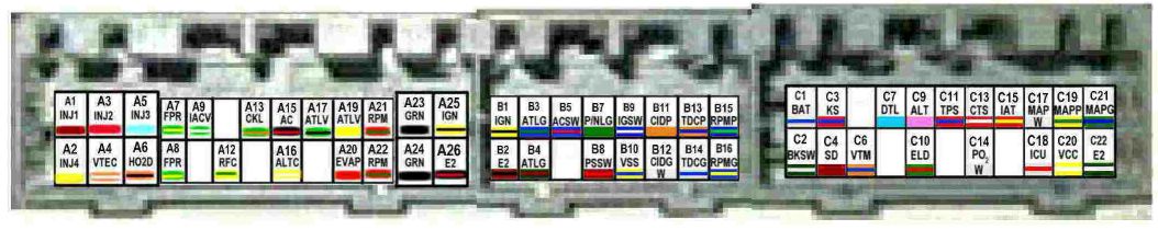
The first one.
The second one would be somewhat more correct if they didn't have that last plug listed as "C", it is supposed to be the "D" plug, as the p28 ecu does not have a "C" plug.
The second one would be somewhat more correct if they didn't have that last plug listed as "C", it is supposed to be the "D" plug, as the p28 ecu does not have a "C" plug.

Thread
Thread Starter
Forum
Replies
Last Post
RACEPAK
Honda Civic / Del Sol (1992 - 2000)
7
09-25-2006 01:34 PM
BlingEG
Honda Civic / Del Sol (1992 - 2000)
1
04-04-2006 03:27 PM