When you click on links to various merchants on this site and make a purchase, this can result in this site earning a commission. Affiliate programs and affiliations include, but are not limited to, the eBay Partner Network.
I need to know where the grounds for the injectors need to end up at the ecu. Currently all four of my injectors have continuity at B1&C10 and the brown red blue yellow wires have continuity at pins A1-7 is this correct???
D15b pm6
I keeping reading to splice or solder five wires together. Which ones lol I�m very curious here are some pics hopefully y�all can point out which ones lol
We need more info. Are you doing a DPFI to MPFI swap, or simply swapping in OBD1 injectors into an already MPFI car so that you can delete the resistor box?
I keeping reading to splice or solder five wires together. Which ones lol I�m very curious here are some pics hopefully y�all can point out which ones lol
They are the 5 wires that plug into the resistor box.
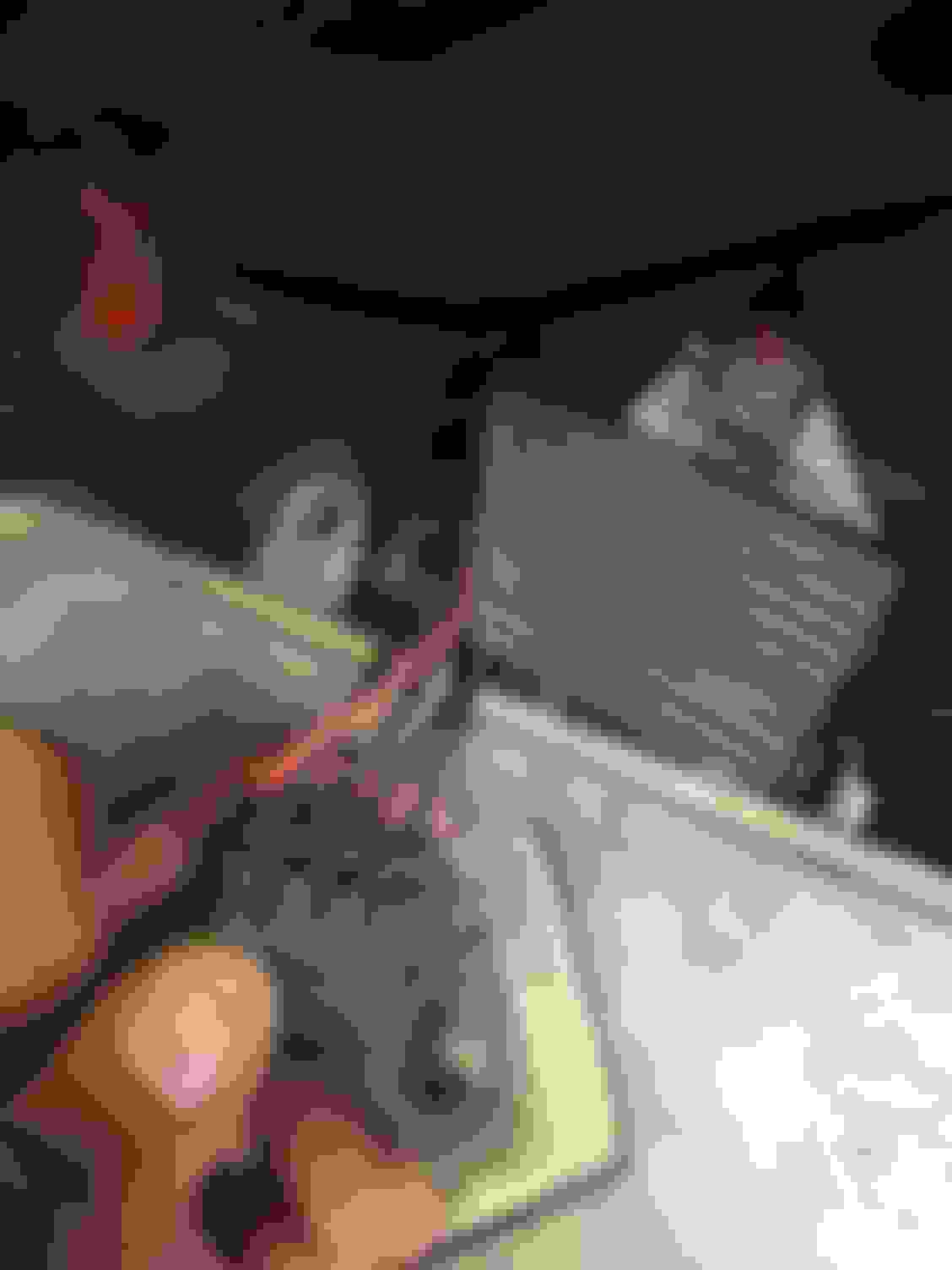
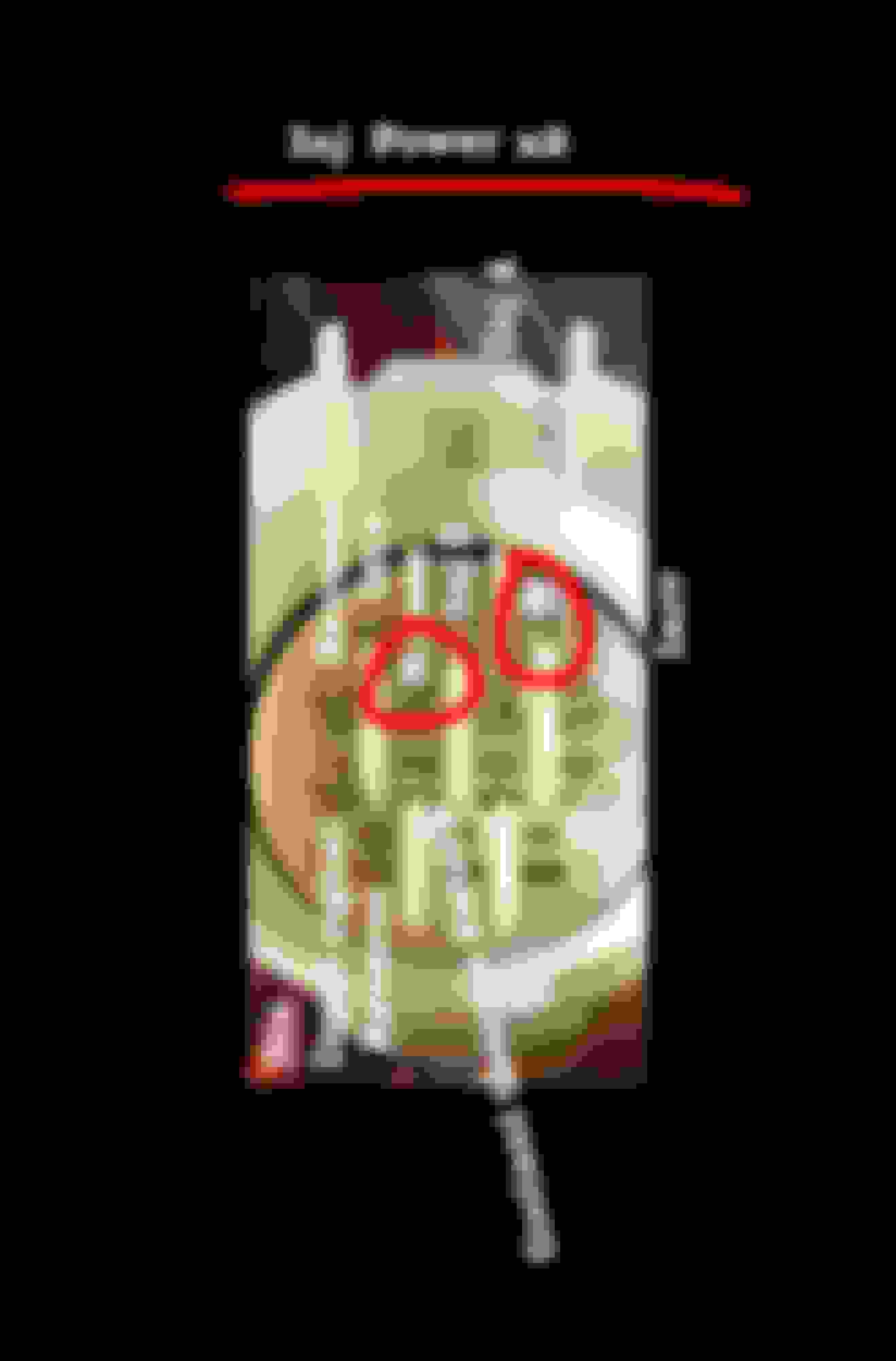
I put a multipoint system on on my d15b2 and I�m trying to get it started with a pm6 ecu. I recently swapped in some obd1 injectors. Here is a picture of the suspected wires I�m supposed to splice together ive labeled them 1-5. Are these supposed to be spliced together and left spliced into the two yellow wires in the back just as they are plugged into the ecu?
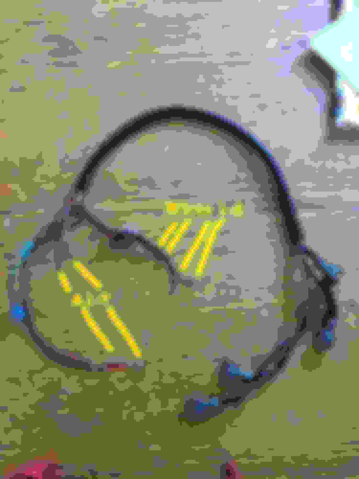
Here is a picture of the stand alone harness that I made for the injectors after I cut it off.
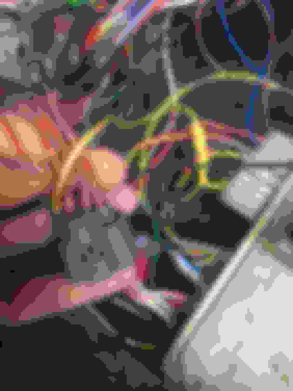
Again I�ve labeled them those that go to pins A1-7 & the wires 1-4 that go to the resistor box blue with the numbered 5 yellow wire. If you follow the single yellow wire back you can see that it�s spliced into wires that go to pins A17&15 even though everyone has it just so y�all don�t have to go find it here�s the Pinot that I�m using.
Now with my new wire harness the red wires 1-4 from the pictures splice into two wires in the harness and goes to two pins at big round plug on the driver side. Here�s a pic
Those two wires have continuity to a few pins at the ecu. Is that right?
Wires 1~4 on your injector harness splice together into a single heavier gauge wire.
(1, 3, 5, 7 individually go to the A1, A3, A5, A7 pins on the ECU)
Most people would do this on the driver side of the car where the D15B2 wiring feeds down tot he main relay.
The main relay then feeds over to the ECU at A13, A15.
You are fine connecting directly at the ECU as you are, but...
1) Do keep in mind that you will have a stray wire from the D15B2 engine harness at the main relay.
2) I would consider NOT connecting power at the ECU only because it is further from the source of power - the main relay.
(The ECU receives power from the main relay on A13 and A15 - ECU does not provide power to the injectors.)
I was reading my opening post is that why it�s called op idk and I was like A18&16 wtf was I high when I wrote that? No I remembered that�s right from the frour red wires at the injector clips continuity went to A18&16 so I came to the idea that they should that I should put those two wires at A15&13 yes or no? Lol maybe what do y�all think? I was trying to wrap my head around thinking how to splice those wires at A18&16 with the yellow wire I numbered 5 lol omg but is that yellow set of wires special and further down the line splice into other things ?! Like the main relay? Is that wire on the main harness on the driver side has continuity to so many pins at the ecu I need to check that again
Wires 1~4 on your injector harness splice together into a single heavier gauge wire.
(1, 3, 5, 7 individually go to the A1, A3, A5, A7 pins on the ECU)
Most people would do this on the driver side of the car where the D15B2 wiring feeds down tot he main relay.
The main relay then feeds over to the ECU at A13, A15.
yea that�s what�s happening now I don�t even have in use anymore that injector harness. I have a brand new wire harness and all four of the red wires at the injector clips aka the wires that would have been 1-4 go to two pins at the big round plug on the driver side. Those two pins have continuity to pins A18&16 at the ecu. I was thinking I should put them in place of the wires at pins A13&15? But would that disturb other circuits is what I was thinking
OP = original poster, aka, the person who started the thread. That's you.
A16 (BRN/BLK) and A18 (BLK/RED) are grounds for the ECU. These go to G101 (thermostat housing ground) via the 14-pin connector on the passenger shock tower. Your injectors are not supposed to connect here.
The four RED/BLK wires at each injector clip need to be connected to a +12V switched source. All four of these RED/BLK wires can get connected together, and then connected to one +12V switched source. This is what the "dead end plug" on OBD1 Civics does - it is a +12V power distribution for the four injectors, and some of the other engine components which need +12V. As 4drEF stated, you can connect these wires to either of the two YEL/BLK wires at the 14-pin plug on the driver's side shock tower.
It won't be the cleanest execution, but if your car ran previously on OBD0 injectors with a resistor box, and you were using the plug pictured here to connect to the resistor box, just run the four RED/BLK wires from the injectors to connect to the big YEL/BLK wire.
Originally Posted by Efmysedan
Originally Posted by Efmysedan
I have a brand new wire harness and all four of the red wires at the injector clips aka the wires that would have been 1-4 go to two pins at the big round plug on the driver side. Those two pins have continuity to pins A18&16 at the ecu. I was thinking I should put them in place of the wires at pins A13&15? But would that disturb other circuits is what I was thinking
If your YEL/BLK wires at the driver's shock tower plug have continuity to A16 and A18, you have a big problem, because you're shorting the main relay (and a host of other things) to ground.
Yea I messed up in my opening post. I edited it just now from A18&16 to B1&C10. Sorry y�all I just went and checked continuity again and I had got it wrong.
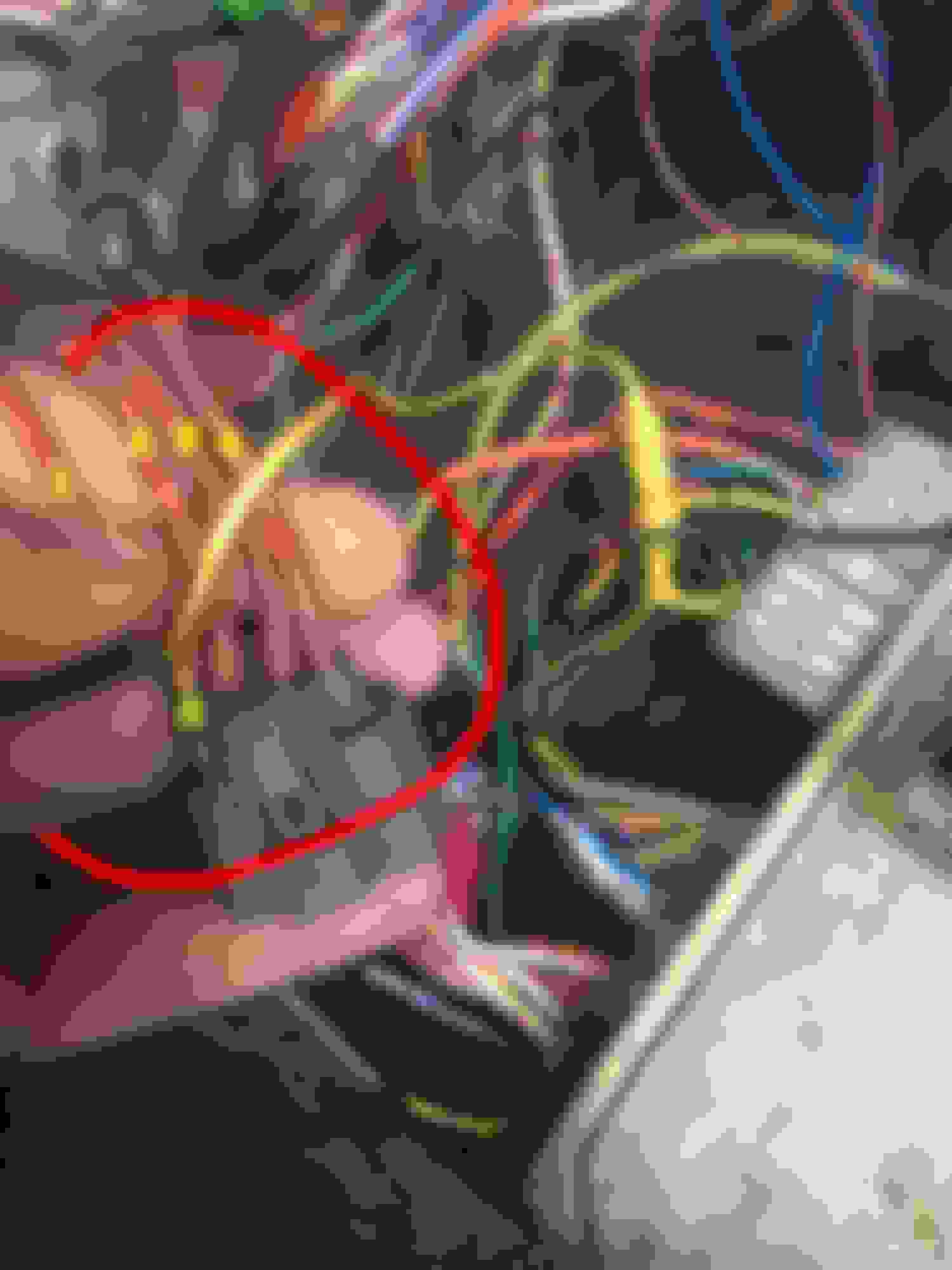
I edited my picture as well. Here�s the new one.
The last one on the bottom I can�t find continuity for. On the engine harness side it goes to the reverse switch but at the ecu plugs I can�t find it. I�ll look again. Anyway back to where I messed up. On my new harnes* The four power wires for the injectors splice to two pins at the big round plug on the driver side. Those two wires from that plug have continuity to wires at pins B1&C10 but idk if I mentioned that with the ignition on there�s power only to where I added a green mark on the plug with a marker. I�ll also fix this other picture where I have the two power wires labeled ground.

 04-18-2019, 11:32 AM