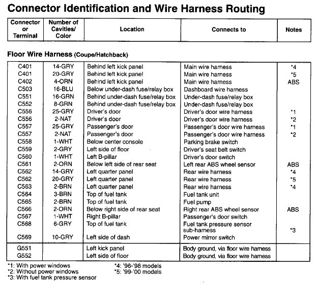
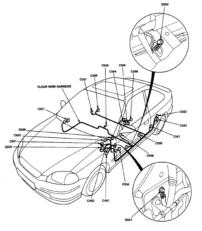
96 civic dx coupe - floor harness pinout diagram
#1
I know this has been asked thousands of times probably but i spent the entire weekend looking and could not find a picture matching mine. After the wife nagging me for weeks to fix the windows, i opted to just replace both regulators and motors. The drivers side was definately the regulator. However after installing the new set in the passengers side, it would still not go down. At first thought it was switch then i decided to follow the you tube video. And to no avail after performing the light test i had to pop out the floor harness to door and guess what i see. 7 loose wires. After cleaning the grease i could finally see the terminals and i de-pinned all the remaining pins and reconnected them. My problem is where do they go, Ive searched and searched but i cannot find any to match what i have. Any help is GREATLY appreciated.


#3
its a 96 dx coupe with power locks / windows. Not sure about heated / defogger mirrors. What I do know are the 7 wire colors are as follows. A pic wont be available till i get home tonight. But the wires that need to beconnected are as follows;
1) Yellow/Red (thicker size wire)
2) White/Black
3) Blue/Yellow
4) Blue/Black
5) Blue/Yellow
6) Green/Black
7) Green/White
The wires that are still connected are as follows starting from the top going to the right (facing the pins not the wires) secondary lock is on the bottom;
White/Green, blank, blank, blank, blank
blank, blank, blank, Blue/Red, blank
blank, White/Red, Blank, Yellow/Red (thinner wire), Blue/Black
Blue, blank, blank, Green/Orange, Blue/Yellow
For the last row i forgot the order the black wires were in but it goes
blank,Black, Black, blank, blank or blank, blank, black, black, blank
#4
its a 96 dx coupe with power locks / windows. Not sure about heated / defogger mirrors. What I do know are the 7 wire colors are as follows. A pic wont be available till i get home tonight. But the wires that need to beconnected are as follows;
1) Yellow/Red (thicker size wire)
2) White/Black
3) Blue/Yellow
4) Blue/Black
5) Blue/Yellow
6) Green/Black
7) Green/White
The wires that are still connected are as follows starting from the top going to the right (facing the pins not the wires) secondary lock is on the bottom;
White/Green, blank, blank, blank, blank
blank, blank, blank, Blue/Red, blank
blank, White/Red, Blank, Yellow/Red (thinner wire), Blue/Black
Blue, blank, blank, Green/Orange, Blue/Yellow
For the last row i forgot the order the black wires were in but it goes
blank,Black, Black, blank, blank or blank, blank, black, black, blank
1) Yellow/Red (thicker size wire)
2) White/Black
3) Blue/Yellow
4) Blue/Black
5) Blue/Yellow
6) Green/Black
7) Green/White
The wires that are still connected are as follows starting from the top going to the right (facing the pins not the wires) secondary lock is on the bottom;
White/Green, blank, blank, blank, blank
blank, blank, blank, Blue/Red, blank
blank, White/Red, Blank, Yellow/Red (thinner wire), Blue/Black
Blue, blank, blank, Green/Orange, Blue/Yellow
For the last row i forgot the order the black wires were in but it goes
blank,Black, Black, blank, blank or blank, blank, black, black, blank
Is there a connector where these wires attach? If so, which one.
#5
not sure if i fully understand the question.
the connectors that the wires attached to in the harness were still in tact (appears that the wires frayed off nothing was corroded). I had to de-pin them from the harness. Then i used the tip to my light tester to unclamp the ends of the pins in order to re-clamp the wires onto them. It took time but i got them all. Ill get the pics up tonight.
the connectors that the wires attached to in the harness were still in tact (appears that the wires frayed off nothing was corroded). I had to de-pin them from the harness. Then i used the tip to my light tester to unclamp the ends of the pins in order to re-clamp the wires onto them. It took time but i got them all. Ill get the pics up tonight.
#6
Trending Topics
#8
#9
The to all, seems like after running the Vin its a ex not a DX. Also for those that know what I mean don't smoke and trace wires at night. I got color blind and mixednthe blue/orange with the blue/red. Thanks again, sorry to waste your time.
Thread
Thread Starter
Forum
Replies
Last Post
EvoMperor
Honda Civic / Del Sol (1992 - 2000)
11
04-22-2008 03:05 PM
mikeaitken
Honda Civic / Del Sol (1992 - 2000)
2
03-07-2006 04:46 PM
97civicdx
Honda Civic / Del Sol (1992 - 2000)
2
05-31-2003 06:43 PM


