
Brakeline tuck
 06-26-2007, 09:38 AM
#1
Honda-Tech Member
Thread Starter
Join Date: Feb 2004
Location: Tulsa, OK, USA
Posts: 282
Likes: 0
Received 0 Likes
on
0 Posts
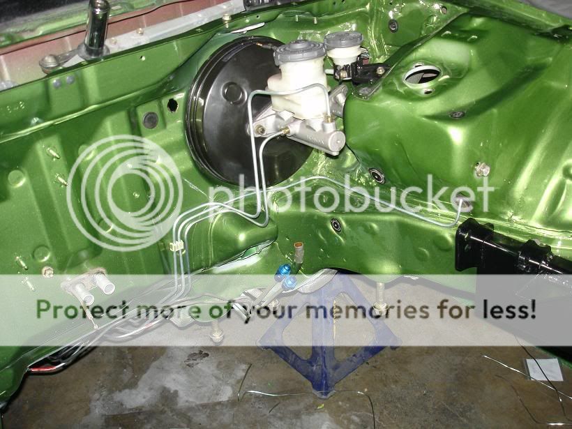
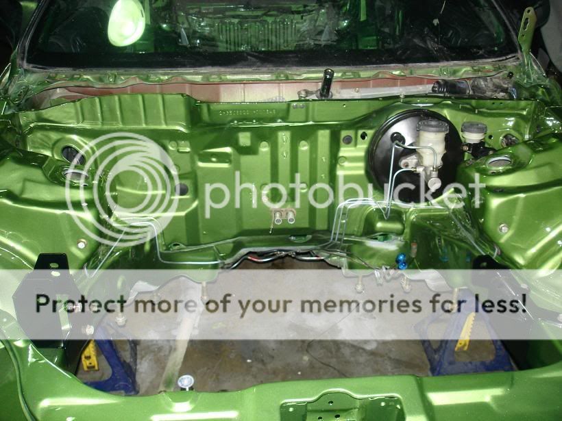
I'm doing a complete wire tuck and brakeline tuck on my 95 RHD Civic coupe. I have the wiring done. Looking for some ideas on how people tucked the brakelines. I have some ideas but looking to see if anyone might have some better ones. I have mounted the proportioning valve about where the SRS control unit would be. I have the brakelines to the rear tucked. I'm looking for a good why to tuck the lines for the master cylinder and the fronts. Come on give me some good ideas and pics too please.
 06-26-2007, 09:44 AM
#2
Junior Member
Join Date: Feb 2002
Location: Lunatic Fringe, ATX
Posts: 598
Likes: 0
Received 0 Likes
on
0 Posts
06-26-2007, 02:58 PM
#3
Honda-Tech Member
Thread Starter
Join Date: Feb 2004
Location: Tulsa, OK, USA
Posts: 282
Likes: 0
Received 0 Likes
on
0 Posts
I have looked through about 100 pages of it and no one really addresses it. I see alot of them shaved but no one going into detail on what they did. I did see one that was the same idea that I already have.
06-27-2007, 11:03 AM
#5
look around dude, there's plenty of people who've posted their setup.
This thread isnt here to tell you how to five lug your car, nor is it here to help you select an aftermarket big brake kit.
Its here to provide a bit of information to those seeking it, those who want to learn more about brake systems and how they work, and to also lend hand in coming up with your own brake system to complement your engine swap,
wire tuck or whatever the case might be.
First, lets start off with the bare basics:
The purpose of your brake system is to slow and stop your vehicle, and hold the vehicle stationary when parked. This is accomplished by using friction between the lining material on non-moving brake pads, brake shoes, rotors and drums. When you apply your brakes, the vehicles kinetic (moving) energy is converted into heat.
The pads are applied against rotors/drums though a hydraulic system that transfers and multiplies the force applied by the driver on the brake pedal.
Your Master Cylinder, Brake lines/Brake hoses, Calipers/Wheel cylinders apply pressure to the brake pads and shoes. Based on this system the Mechanical force
from your foot pressing on the brake pedal is turned into hydraulic fluid pressure.
For those of us with ABS (anti-lock brakes), it is a system on the vechicle that controls heavy braking by releasing hydraulic pressure to the wheels that are about to lock up and skid. ABS sensors are located at the wheels, and they monitor rotating wheel speed in relation to a control module that in turn controls a hydraulic modulator,
wich regulates hydraulic fluid pressure to each brake assembly.
Now that we know the most common principle to the brake system is hydralic pressure, here is how it came about.
Blaise Pascal was a 17th century scientist that discovered two primary characteristics about the behavior of fluids contained within a closed space. First being that Fluids
CANNOT be compressed. Second, when a pressure is applied to a liquid within a closed space, pressure is exerted equally in all directions. Thus being "Pascal's Law"
Since liquids do not have a definate form of their own and are not compressable, they will conform to the shape of any container they are put into. This property offeres a
distinct advantage for any type of system that works on hydraulic pressure.
IF you were to push down on your brake pedal and exert 200psi of pressure onto the master cylinder, you would also create 200psi on any point of your brake system due to these properties.
Here is a good formula to find what your system pressure is.
Force at Master Cylinder
___________________________ = System Pressure
Master Cylinder Piston Area
Now, if you take the system pressure of "X" Amount expressed in PSI, by the "X" sq. inch area of the wheel cylinder piston you can determine the final pressure exerted by the cylinders on the wheel cylinder by using the formula
System pressure x Wheel cylinder piston area = final pressure
The second equation is geared twoards vehicles with rear drum brakes
Another important aspect is there is a fixed relationship between motion/travel and the area of the pistons used in the brake system.
A good example:
If a 1 sq. inch master cylinder piston moves 1 inch and the wheel cylinder piston is the same size, then the maximum travel of the wheel cylinder will be 1 inch. However
the larger the wheel sylinder piston, the less distance it will travel.
Since pistons used in wheel cylinders/calipers are always larger than a master cylinder their motion/travel will always be extremely limited. Even during a panic stop situation when the brake pedal travels the farthest, caliper and wheel cylinder pistons move very little.
The hydraulic brake system only takes small initial pressure to generate the enourmous amount of force needed to stop a moving vehicle.
The centerpiece of the hydraulic brake system is the Master Cylinder. Its purpose is to transfer the drivers foot force on the brake pedal into hydraulic pressure. Today Master Cylinders are made of either cast iron with integral fluid resevoirs, or aluminum with a separate fiberglass reinforced plastic resevoir. The aluminum master cylinders
are anodized to help protect against corrosion, and helps extend the life of the cylinder bore.
History on the Master cylinder:
Master cylinders vary on how may pistons they use, but the action of all master cylinders is the same. The single circuit hydraulic brake system was used on cars bulit through 1966 this system was ran on a single piston master cylinder that operate the brakes on all four wheels.
In 1967, a legislation was passed that required all cars to come with two separate brake systems.
The dual brake system differes from the single setup, in that it uses a tandem master cylinder.
Now master cylinders encorporate two pistons inside of one cylinder bore. This is why on hondas and every other car you will find at least two fittings on the master cylinder. The fitting closest to the firewall will be the primary piston. The fitting farthest from the firewall
will be the secondary piston. On early dual brake systems they were setup putting 50% of braking power to the front brakes, and 50% to the rear. If one failed, it would leave the other end of the vehicle to stop the entire car, seeing as the front brakes do most of the work this could cause
trouble if the front circuit was to go out.
This is when the diagonally split circuit came into play. Its the same principle as the front/rear split system but the primary piston acts on two opposite corners, and the secondary piston acts on two opposite corners, leaving at least 50% of the braking power at the drivers disposal.
Now, if anyone would like to know in detal of how a dual master cylinder works, what kinds of parts make up the dual master cylinder, or anything else involving the master cylinder feel free to PM me or post in this thread and I will happily return with the best answer I can give.
Next topic, is the Proportioning Valve. Many of you have swapped yours to encorporate rear disc brakes or for the 5 lug conversion.
The proportioning valve improves front-to-rear brake balance under high deceleration or panic stops.
Under hard stopping conditions a percentage of the vehicles rear weight is transferred to the front wheels, and as the rear end becomes lighter the tendency tof the rear brakes to lock up increases, therefore the "P-Valve" or "PV" is used to control rear brake pressures partiularly in hard stops.
When pressure to the rear brakes reaches a predetermined level (specified by honda/acura) the PV overcomes the force of its spring loaded piston and stops the flow of fluid to the rear brakes. this keeps the brake system pressure at a lower level than the front brakes, and keeps the front/rear braking forces in sync.
Almost done with the boring parts, take a break if you must.
For those of us with ABS (anti-lock Brakes)
Here is a quick description of the system.
99% of the time when you encounter a situation where you need to stop fast, you slam down the pedal and keep it depressed. Without ABS this would cause you to lock up the wheels, skid and possibly wreck and loose control of your vehicle. Thats why your parents probably told you to pump the brakes up on your first car when you slide around in the ice, or nearly tag someones rear-end at the school parking lot when you shouldnt have been staring at the cute brunette walking by.
ABS does that pumping for you, and at a rate much faster and much more precise than anything a person could achieve.
as stated before ABS systes use a control module in conjunction with a group of wheel speed sensors to establish the deceleration rate of the vehicles wheels during braking. If the module thinks one of your wheels is about to lock up it will issue the neccesary commants to a hydraulic modulator, and inturn the modulator regulates fluid pressure to the particular wheel as instructed by the module
You have three phases of hydraulic control that occour during a hard, or ABS stop.
First = Pressure maintain phase meaning that any futher brake fluid pressure to the slipping wheel, or wheels is cut off.
Second = Pressure decrease function, if wheel slip continues to increas in the first phase hydraulic pressure to the wheels is then decreaes until wheel slip approaches zero. This means that wheel speed equals vehicle speed, and at this ponit the first stage is re-ingaged.
third = This is the pressure increase stage. If your wheel slipl approaches zero in the pressure maintain stage, pressure to the wheels is increaed until wheel slip begins to occour, meaning that wheel speed is less than vehicle speed. the pressure increase stage is another term for normal brake operation, since maximum master cylinder pressure is applied to the wheels.
quick-tip for other makes and models with ABS:
systems can be categorized according to system type (integral and non-integral) number of wheels covered in the system (two-wheel and four-wheel) and number of channels (one, two, three, or four channel)
There it is for the basics of brake systems.
I tried to apply the most basic things twoard's our hondas. Obviously the three hottest platforms would be the EG, EK, and DC2, and im not very aware of the brake systems newer honda/acura's use. Unfortuneately being a tech at mr. goodyear leads me to working on things i'd rather not work on, and rarely do i see a honda in the shop.
As I already said once, if anyone has questions about any particular part of the brake system i'd be more than happy to give you the best answer i can, and i about memorzied the entire ASE study guide for brakes so you can trust what I say.
Anything works, from a more descriptive explanation of master cylinders, proportioning valves, types of brake fluids and chemical compounds, pushrods, proper ways to bench bleed, brake lines and hoses, metering valves combination valves, pressure differential valves and switches, height sensing proportioning valves, step-bore quick take up master cylinders, the list goes on...ask any question, were all here to learn.
So now if your wondering if I have a life, well i'd like to think so. :silly:
Anyways, to the fun stuff.
Many people have sent me private messages about what i was using, and how was I doing my brake lines on my EK.
Now I will gladly give you a part numbers, and things to consider while doing this, but you must come up with your own design using your own creativity to make it your own. I personally had my system ran three different times before I finally liked what I saw, or for better words...didnt see. (thanks to Bads2k for talking me into putting mine inside of the car)
What Im going to cover now is a quick list of parts that I used to make my setup.
Purchased from Oreilly Auto Parts
3/16ths STEEL Brake line
Part # BL360
List price: $8.46 + tax per line
- That was the longest straight piece of line they had in stock, there are shorter lines
available.
Tubing Bender
Part # W80674
List Price $16.93 + tax
- there are better tubing benders on the market, but this was cheap and I will probably never
use it again after my lines are finished, thats why I used the cheaper one.
Note on the tubing bender:
You can bend the lines however you want, with whatever you want. For a good amount of time while I was doing my lines I actually had a broom-handle clamped down in a vise to achieve tighter bends. Any bend in the line is OK as long as you do not kink the line in the process.
Flaring Tool
Snap-on Double Flaring tool
part # TFM5A
Price $45.30 Buy online or through your local dealer.
note for flaring tools:
Again many different options for flaring tools are on the market. Some come with tubing benders, etc. I'd look at harbour freight, or another store of the sort to find a more affordable double flaring tool that you can use for your build, and not worry about blowing $50.00 on. Metric and standard flaring tools are available as well from a wide variety of manufacturers.
keep in mind, DOUBLE flare tool.
Now that you know a thing or two about proportioning valves, you should know that these operate purely on hydraulic pressure, gravity has no affect. What this means to me, is that now I can mount my proportioning valve anywhere I want. On the subframe, under the battery, or even in the backseat. Possibilities are endless.
Now, theres one thing you need to decide. Where are you going to put your proportioning valve?
I personally Put it in three different places before I decided to put it behind the Firewall, on the inside of the vehicle.
as a friendly reminder, i'd recommend taking note of the proportioning valve and each line running to it, and draw yourself a small picture that you can use as a reference for each pipe heading into and out of the valve, otherwise your valve isnt going to do you any good, you want your left front brakes to be in the left front spot on the valve, and so on.
I personally did one line as a time, and used the factory lines as a reference to help aid in my new bends.
Now, bending the lines and running them however you please is completely on you. My only tip for bending lines is dont kink the lines, if you do kink a line keep going with it and get yourself a good mockup, then re-bend a new line
and fit it tight into place.
My other tip for your new lines, is re-use your factory 10mm fittings, because the 3/16ths fittings you get on the line will fit loosely (thanks to CRXbart for that tip).
however, save the shorter 3/16ths fittings you will get on the line, because they might come in handy later on in the
process.
Not everyone has line-wrenches to take off fittings kept on a line, but if your going to use pliers or an opend end wrench be very careful not to mess the fittings up, otherwise be ready to buy new ones. They will brake, fair warning.
next up would be flaring the lines.
Flare LAST, this will leave you extra slack on each end so you dont end up too short and have to start all over.
Heres a typical double flare tool

-You see a tubing cutter at the top right
-flaring bar at the bottom right
-yoke in the center
-adaptors on the far left for making double flares.
the small adaptors are key to making the double flare.
Now, seeing as ive been using 3/16ths line, you will want to get a flare tool that flares standard/fractional lines.
major name companies also make metric flaring tools.
so, if your going to use a fractional line, get a fractional double flare tool, 45 degree flare!
another good tip, is when you are cutting line, cut slowly and take your time. This will ensure that you get a smoother cut and keep the roundness of the line. Check to make sure there isnt any scrap metal near the hole in your line.
Heres how I start the flaring process.

Now, the first step to flaring is to put your 3/16ths line into the slot on your flaring bar designated for 3/16ths line.

second, is take your 3/16ths adaptor and line the line up with the height of the base (not the nipple)

As you can see, not very much of the line is sticking out of the flaring bar.
Third, With the line clamped down tight in the flaring bar, put the nipple of the adaptor into the line, and the yoke on top of the adaptor to provide force to create the first flare.

after being pressed down using the yoke

now, after youve created the first flare, you want to bring the yoke off of your adaptor and pull the adaptor away. you might not even be able to tell that the line has even been flared, but you will be able to see that its been pressed back further into the flaring bar.
Fourth step would be to create your final flare, the 45 degree. After removing the 3/16ths adaptor screw the yoke down into the hole in your line as so.

Next step is to press the yoke down into the line. This might get some getting used to so that you have the proper feel for when you need to back off, but most of the time you can just bottom the yoke out in the flaring bar and be fine.
heres what you should see.

bring the yoke away from the line once again, remove it from the flaring bar and then remove your line from the bar.
Check your new flare for any imperfections, and check to see how uniform the lip of the flare is. This is an important thing that shouldnt be passed up. The flare is your seal for the lines, and it could also mean having and not having brakes, take caution to prevent anything bad from happening to your car and more importantly yourself.
Now, hopefully you didnt forget to slide your fitting on before you flared the lines.
Heres what you should see after all is said and done.

I hope everyone could learn somthing from this writeup. Knowing the phrase "theres always someone out there thats smarter than you" feel free to add anything to this post that you feel is neccesary. Feedback appreciated :up:
Its here to provide a bit of information to those seeking it, those who want to learn more about brake systems and how they work, and to also lend hand in coming up with your own brake system to complement your engine swap,
wire tuck or whatever the case might be.
First, lets start off with the bare basics:
The purpose of your brake system is to slow and stop your vehicle, and hold the vehicle stationary when parked. This is accomplished by using friction between the lining material on non-moving brake pads, brake shoes, rotors and drums. When you apply your brakes, the vehicles kinetic (moving) energy is converted into heat.
The pads are applied against rotors/drums though a hydraulic system that transfers and multiplies the force applied by the driver on the brake pedal.
Your Master Cylinder, Brake lines/Brake hoses, Calipers/Wheel cylinders apply pressure to the brake pads and shoes. Based on this system the Mechanical force
from your foot pressing on the brake pedal is turned into hydraulic fluid pressure.
For those of us with ABS (anti-lock brakes), it is a system on the vechicle that controls heavy braking by releasing hydraulic pressure to the wheels that are about to lock up and skid. ABS sensors are located at the wheels, and they monitor rotating wheel speed in relation to a control module that in turn controls a hydraulic modulator,
wich regulates hydraulic fluid pressure to each brake assembly.
Now that we know the most common principle to the brake system is hydralic pressure, here is how it came about.
Blaise Pascal was a 17th century scientist that discovered two primary characteristics about the behavior of fluids contained within a closed space. First being that Fluids
CANNOT be compressed. Second, when a pressure is applied to a liquid within a closed space, pressure is exerted equally in all directions. Thus being "Pascal's Law"
Since liquids do not have a definate form of their own and are not compressable, they will conform to the shape of any container they are put into. This property offeres a
distinct advantage for any type of system that works on hydraulic pressure.
IF you were to push down on your brake pedal and exert 200psi of pressure onto the master cylinder, you would also create 200psi on any point of your brake system due to these properties.
Here is a good formula to find what your system pressure is.
Force at Master Cylinder
___________________________ = System Pressure
Master Cylinder Piston Area
Now, if you take the system pressure of "X" Amount expressed in PSI, by the "X" sq. inch area of the wheel cylinder piston you can determine the final pressure exerted by the cylinders on the wheel cylinder by using the formula
System pressure x Wheel cylinder piston area = final pressure
The second equation is geared twoards vehicles with rear drum brakes
Another important aspect is there is a fixed relationship between motion/travel and the area of the pistons used in the brake system.
A good example:
If a 1 sq. inch master cylinder piston moves 1 inch and the wheel cylinder piston is the same size, then the maximum travel of the wheel cylinder will be 1 inch. However
the larger the wheel sylinder piston, the less distance it will travel.
Since pistons used in wheel cylinders/calipers are always larger than a master cylinder their motion/travel will always be extremely limited. Even during a panic stop situation when the brake pedal travels the farthest, caliper and wheel cylinder pistons move very little.
The hydraulic brake system only takes small initial pressure to generate the enourmous amount of force needed to stop a moving vehicle.
The centerpiece of the hydraulic brake system is the Master Cylinder. Its purpose is to transfer the drivers foot force on the brake pedal into hydraulic pressure. Today Master Cylinders are made of either cast iron with integral fluid resevoirs, or aluminum with a separate fiberglass reinforced plastic resevoir. The aluminum master cylinders
are anodized to help protect against corrosion, and helps extend the life of the cylinder bore.
History on the Master cylinder:
Master cylinders vary on how may pistons they use, but the action of all master cylinders is the same. The single circuit hydraulic brake system was used on cars bulit through 1966 this system was ran on a single piston master cylinder that operate the brakes on all four wheels.
In 1967, a legislation was passed that required all cars to come with two separate brake systems.
The dual brake system differes from the single setup, in that it uses a tandem master cylinder.
Now master cylinders encorporate two pistons inside of one cylinder bore. This is why on hondas and every other car you will find at least two fittings on the master cylinder. The fitting closest to the firewall will be the primary piston. The fitting farthest from the firewall
will be the secondary piston. On early dual brake systems they were setup putting 50% of braking power to the front brakes, and 50% to the rear. If one failed, it would leave the other end of the vehicle to stop the entire car, seeing as the front brakes do most of the work this could cause
trouble if the front circuit was to go out.
This is when the diagonally split circuit came into play. Its the same principle as the front/rear split system but the primary piston acts on two opposite corners, and the secondary piston acts on two opposite corners, leaving at least 50% of the braking power at the drivers disposal.
Now, if anyone would like to know in detal of how a dual master cylinder works, what kinds of parts make up the dual master cylinder, or anything else involving the master cylinder feel free to PM me or post in this thread and I will happily return with the best answer I can give.
Next topic, is the Proportioning Valve. Many of you have swapped yours to encorporate rear disc brakes or for the 5 lug conversion.
The proportioning valve improves front-to-rear brake balance under high deceleration or panic stops.
Under hard stopping conditions a percentage of the vehicles rear weight is transferred to the front wheels, and as the rear end becomes lighter the tendency tof the rear brakes to lock up increases, therefore the "P-Valve" or "PV" is used to control rear brake pressures partiularly in hard stops.
When pressure to the rear brakes reaches a predetermined level (specified by honda/acura) the PV overcomes the force of its spring loaded piston and stops the flow of fluid to the rear brakes. this keeps the brake system pressure at a lower level than the front brakes, and keeps the front/rear braking forces in sync.
Almost done with the boring parts, take a break if you must.
For those of us with ABS (anti-lock Brakes)
Here is a quick description of the system.
99% of the time when you encounter a situation where you need to stop fast, you slam down the pedal and keep it depressed. Without ABS this would cause you to lock up the wheels, skid and possibly wreck and loose control of your vehicle. Thats why your parents probably told you to pump the brakes up on your first car when you slide around in the ice, or nearly tag someones rear-end at the school parking lot when you shouldnt have been staring at the cute brunette walking by.
ABS does that pumping for you, and at a rate much faster and much more precise than anything a person could achieve.
as stated before ABS systes use a control module in conjunction with a group of wheel speed sensors to establish the deceleration rate of the vehicles wheels during braking. If the module thinks one of your wheels is about to lock up it will issue the neccesary commants to a hydraulic modulator, and inturn the modulator regulates fluid pressure to the particular wheel as instructed by the module
You have three phases of hydraulic control that occour during a hard, or ABS stop.
First = Pressure maintain phase meaning that any futher brake fluid pressure to the slipping wheel, or wheels is cut off.
Second = Pressure decrease function, if wheel slip continues to increas in the first phase hydraulic pressure to the wheels is then decreaes until wheel slip approaches zero. This means that wheel speed equals vehicle speed, and at this ponit the first stage is re-ingaged.
third = This is the pressure increase stage. If your wheel slipl approaches zero in the pressure maintain stage, pressure to the wheels is increaed until wheel slip begins to occour, meaning that wheel speed is less than vehicle speed. the pressure increase stage is another term for normal brake operation, since maximum master cylinder pressure is applied to the wheels.
quick-tip for other makes and models with ABS:
systems can be categorized according to system type (integral and non-integral) number of wheels covered in the system (two-wheel and four-wheel) and number of channels (one, two, three, or four channel)
There it is for the basics of brake systems.
I tried to apply the most basic things twoard's our hondas. Obviously the three hottest platforms would be the EG, EK, and DC2, and im not very aware of the brake systems newer honda/acura's use. Unfortuneately being a tech at mr. goodyear leads me to working on things i'd rather not work on, and rarely do i see a honda in the shop.
As I already said once, if anyone has questions about any particular part of the brake system i'd be more than happy to give you the best answer i can, and i about memorzied the entire ASE study guide for brakes so you can trust what I say.
Anything works, from a more descriptive explanation of master cylinders, proportioning valves, types of brake fluids and chemical compounds, pushrods, proper ways to bench bleed, brake lines and hoses, metering valves combination valves, pressure differential valves and switches, height sensing proportioning valves, step-bore quick take up master cylinders, the list goes on...ask any question, were all here to learn.
So now if your wondering if I have a life, well i'd like to think so. :silly:
Anyways, to the fun stuff.
Many people have sent me private messages about what i was using, and how was I doing my brake lines on my EK.
Now I will gladly give you a part numbers, and things to consider while doing this, but you must come up with your own design using your own creativity to make it your own. I personally had my system ran three different times before I finally liked what I saw, or for better words...didnt see. (thanks to Bads2k for talking me into putting mine inside of the car)
What Im going to cover now is a quick list of parts that I used to make my setup.
Purchased from Oreilly Auto Parts
3/16ths STEEL Brake line
Part # BL360
List price: $8.46 + tax per line
- That was the longest straight piece of line they had in stock, there are shorter lines
available.
Tubing Bender
Part # W80674
List Price $16.93 + tax
- there are better tubing benders on the market, but this was cheap and I will probably never
use it again after my lines are finished, thats why I used the cheaper one.
Note on the tubing bender:
You can bend the lines however you want, with whatever you want. For a good amount of time while I was doing my lines I actually had a broom-handle clamped down in a vise to achieve tighter bends. Any bend in the line is OK as long as you do not kink the line in the process.
Flaring Tool
Snap-on Double Flaring tool
part # TFM5A
Price $45.30 Buy online or through your local dealer.
note for flaring tools:
Again many different options for flaring tools are on the market. Some come with tubing benders, etc. I'd look at harbour freight, or another store of the sort to find a more affordable double flaring tool that you can use for your build, and not worry about blowing $50.00 on. Metric and standard flaring tools are available as well from a wide variety of manufacturers.
keep in mind, DOUBLE flare tool.
Now that you know a thing or two about proportioning valves, you should know that these operate purely on hydraulic pressure, gravity has no affect. What this means to me, is that now I can mount my proportioning valve anywhere I want. On the subframe, under the battery, or even in the backseat. Possibilities are endless.
Now, theres one thing you need to decide. Where are you going to put your proportioning valve?
I personally Put it in three different places before I decided to put it behind the Firewall, on the inside of the vehicle.
as a friendly reminder, i'd recommend taking note of the proportioning valve and each line running to it, and draw yourself a small picture that you can use as a reference for each pipe heading into and out of the valve, otherwise your valve isnt going to do you any good, you want your left front brakes to be in the left front spot on the valve, and so on.
I personally did one line as a time, and used the factory lines as a reference to help aid in my new bends.
Now, bending the lines and running them however you please is completely on you. My only tip for bending lines is dont kink the lines, if you do kink a line keep going with it and get yourself a good mockup, then re-bend a new line
and fit it tight into place.
My other tip for your new lines, is re-use your factory 10mm fittings, because the 3/16ths fittings you get on the line will fit loosely (thanks to CRXbart for that tip).
however, save the shorter 3/16ths fittings you will get on the line, because they might come in handy later on in the
process.
Not everyone has line-wrenches to take off fittings kept on a line, but if your going to use pliers or an opend end wrench be very careful not to mess the fittings up, otherwise be ready to buy new ones. They will brake, fair warning.
next up would be flaring the lines.
Flare LAST, this will leave you extra slack on each end so you dont end up too short and have to start all over.
Heres a typical double flare tool
-You see a tubing cutter at the top right
-flaring bar at the bottom right
-yoke in the center
-adaptors on the far left for making double flares.
the small adaptors are key to making the double flare.
Now, seeing as ive been using 3/16ths line, you will want to get a flare tool that flares standard/fractional lines.
major name companies also make metric flaring tools.
so, if your going to use a fractional line, get a fractional double flare tool, 45 degree flare!
another good tip, is when you are cutting line, cut slowly and take your time. This will ensure that you get a smoother cut and keep the roundness of the line. Check to make sure there isnt any scrap metal near the hole in your line.
Heres how I start the flaring process.
Now, the first step to flaring is to put your 3/16ths line into the slot on your flaring bar designated for 3/16ths line.
second, is take your 3/16ths adaptor and line the line up with the height of the base (not the nipple)
As you can see, not very much of the line is sticking out of the flaring bar.
Third, With the line clamped down tight in the flaring bar, put the nipple of the adaptor into the line, and the yoke on top of the adaptor to provide force to create the first flare.
after being pressed down using the yoke
now, after youve created the first flare, you want to bring the yoke off of your adaptor and pull the adaptor away. you might not even be able to tell that the line has even been flared, but you will be able to see that its been pressed back further into the flaring bar.
Fourth step would be to create your final flare, the 45 degree. After removing the 3/16ths adaptor screw the yoke down into the hole in your line as so.
Next step is to press the yoke down into the line. This might get some getting used to so that you have the proper feel for when you need to back off, but most of the time you can just bottom the yoke out in the flaring bar and be fine.
heres what you should see.
bring the yoke away from the line once again, remove it from the flaring bar and then remove your line from the bar.
Check your new flare for any imperfections, and check to see how uniform the lip of the flare is. This is an important thing that shouldnt be passed up. The flare is your seal for the lines, and it could also mean having and not having brakes, take caution to prevent anything bad from happening to your car and more importantly yourself.
Now, hopefully you didnt forget to slide your fitting on before you flared the lines.
Heres what you should see after all is said and done.
I hope everyone could learn somthing from this writeup. Knowing the phrase "theres always someone out there thats smarter than you" feel free to add anything to this post that you feel is neccesary. Feedback appreciated :up:
06-27-2007, 11:18 AM
#6
Honda-Tech Member
Join Date: Sep 2001
Location: The burbs of illadelph, USA
Posts: 6,045
Likes: 0
Received 1 Like
on
1 Post
<TABLE WIDTH="90%" CELLSPACING=0 CELLPADDING=0 ALIGN=CENTER><TR><TD>Quote, originally posted by fventura03 »</TD></TR><TR><TD CLASS="quote">look around dude, there's plenty of people who've posted their setup.
</TD></TR></TABLE>
you should have let him struggle looking a little bit more
Thats everything you should ever need to know
</TD></TR></TABLE>
you should have let him struggle looking a little bit more
Thats everything you should ever need to know
06-27-2007, 11:49 AM
#7
B*a*n*n*e*d
Join Date: May 2003
Location: The lou
Posts: 691
Likes: 0
Received 0 Likes
on
0 Posts
<TABLE WIDTH="90%" CELLSPACING=0 CELLPADDING=0 ALIGN=CENTER><TR><TD>Quote, originally posted by Chronicsinners »</TD></TR><TR><TD CLASS="quote">you should have let him struggle looking a little bit more
Thats everything you should ever need to know</TD></TR></TABLE>
and more.
Thats everything you should ever need to know</TD></TR></TABLE>
and more.
Trending Topics
06-27-2007, 11:59 AM
#8
Honda-Tech Member
Join Date: Dec 2004
Location: South East, Pa
Posts: 2,082
Likes: 0
Received 0 Likes
on
0 Posts
If you want to be really cool, you could always drill a hole in the firewall and run the lines in and behind there. That's tucked. Throw a rubber grommet around the hole though, as well as some wrap for the lines to make yourseslf feel extra special.
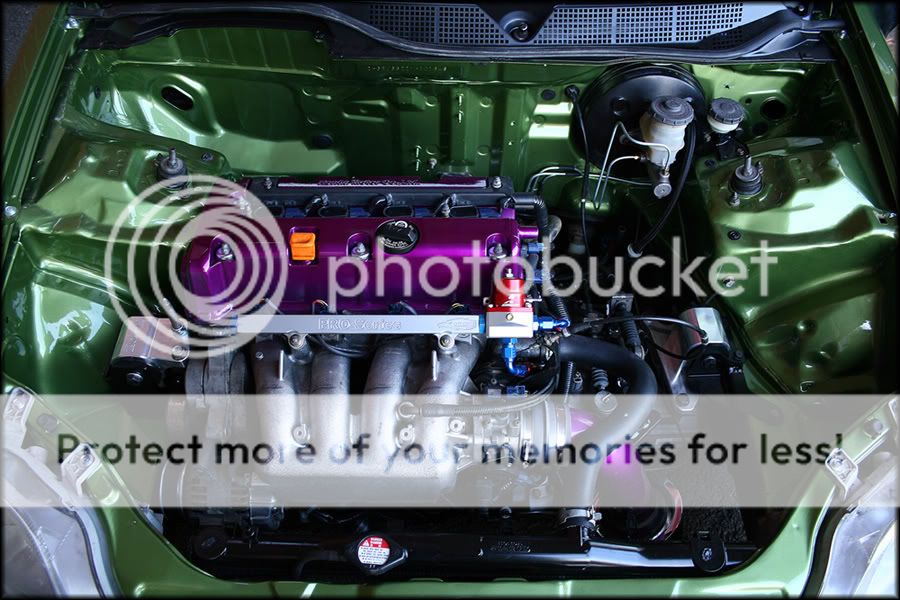
If you're running "steel" lines, instead of braided. Then i'd do the k20 tuck above since steel tubing is hard to manifest in tight areas.
If you're running "steel" lines, instead of braided. Then i'd do the k20 tuck above since steel tubing is hard to manifest in tight areas.
06-27-2007, 01:17 PM
#9
Honda-Tech Member
Thread Starter
Join Date: Feb 2004
Location: Tulsa, OK, USA
Posts: 282
Likes: 0
Received 0 Likes
on
0 Posts
I have been looking but i search for brakeline tuck and various ways of that and not really finding anything helpful. I think i'm going to run them through the firewall with grommets. The CRX has grommets for the brakelines through the firewall so I'm going to go that route I think.
I didn't know if anyone was using something like a bulkhead connector and running part braided steel lines and part metal lines. But it will cost alot of money to convert the lines over to a different size to run braided lines.
I didn't know if anyone was using something like a bulkhead connector and running part braided steel lines and part metal lines. But it will cost alot of money to convert the lines over to a different size to run braided lines.
06-28-2007, 07:54 AM
#10
Junior Member
Join Date: Feb 2002
Location: Lunatic Fringe, ATX
Posts: 598
Likes: 0
Received 0 Likes
on
0 Posts
Do it right and use bulkhead connectors. No need to run braided lines, hardline will work fine. And if you go through the other 200 pages of that thread, you will find more ideas. I just figured that if you wanted it bad enough, you'd be willing to do the research, or just tackle it on your own.

Thread
Thread Starter
Forum
Replies
Last Post
eghatch9295
Mid-West (Sales)
11
05-07-2012 10:21 PM
Black-Ty [EG6]
Southern California (Sales)
17
02-02-2011 07:51 AM