
Need help with cam/crank sensor settings for Megasquirt 3 PRO
 04-30-2014, 03:34 AM
#1
Who is Mr Robot?
Thread Starter
iTrader: (2)
Join Date: Jul 2004
Location: ATL - Where the Pimps and Players dwell
Posts: 21,474
Likes: 0
Received 10 Likes
on
10 Posts
Ok, so I'm going to be using a Megasquirt 3 PRO on my build, which is based on the MS3X architecture but with more built in features, I/O, logic level spark and fuel, etc. I'm going to be running coil on plug using ls2 truck coils since the MS3PRO will control up to 8 logic level spark outputs directly from the ecu. There's also no need for me to go with a T1 style cam trigger as the MS3PRO will work with any oem sensor combo. Plus I'm running a tall deck block so I need a secondary tensioner on the front of the head.
There aren't any real install diagrams as this is a "universal" ECU and flying lead harness (guides are being developed) but since it's based on the MS3X platform I'm using the MS3X honda guide as a rough starting point.
Now, my chassis is OBD2A so I have 4 sensors total, 3 in the distributor and 1 on the crank.
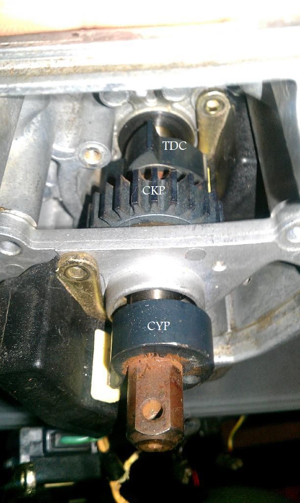
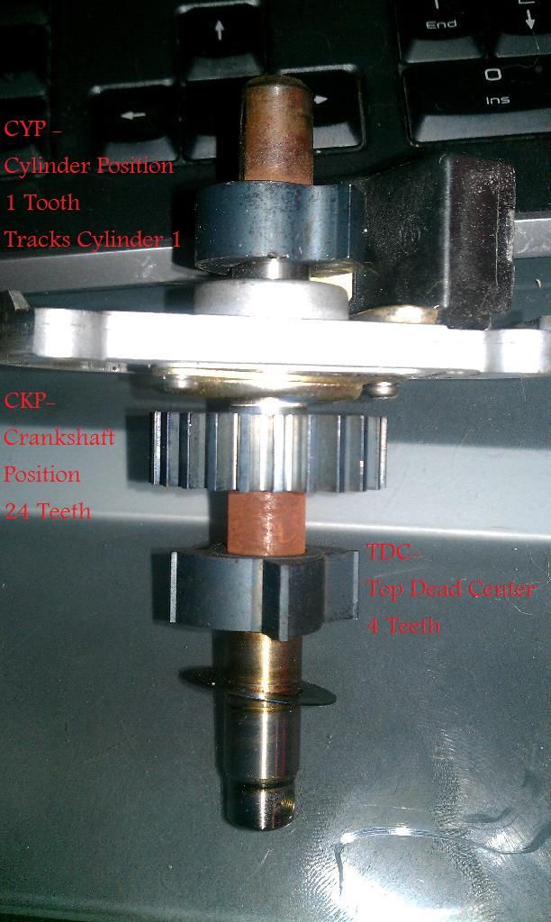
Distributor
CYP - Cylinder Position, 1 tooth. It tracks Cylinder 1 ATDC, something like 45 or 60 degrees ATDC? I don't know exactly
CKP - Crankshaft Position, 24 Teeth
TDC - Top Dead Center, 4 Teeth
Crankshaft
CKF - Crankshaft Fluctuation, 12 Teeth
Images just in case it helps
Distributor
CKF

Now, megasquirt, for direct coil on plug use says you can just use the TDC sensor and ignore everything else. This honestly doesn't make any sense to me because without knowing crankshaft position the ecu cannot determine which tooth on the TDC wheel correlates to what cylinder. unless they were saying use the CKP and TDC... the guide is pretty vague here.
I've also heard of them using the CKP and CYP triggers, you simply have to know at what degree the CYP is oriented to and from what I understand some honda oem distributors have them oriented differently. I've also heard that when people use this combination that they get signal noise from the CKP despite the MS3PRO having signal conditioners on it's VR/Hall inputs. Also using the 24 tooth CKP wheel means that it is effectively a 12 tooth wheel, as there's 2 crank rotations for every 1 cam rotation.
I don't have to use the CKF... The obd2 ecu uses the CKP in the distributor as it's main crankshaft trigger. It simply monitors the CKF to check that timing is "sync'd" between the crank and camshaft and it monitors for any misfires. For emissions purposes I could simply splice the CKP signal to the CKF pins on the ecu and it wouldn't know the difference. However given the CKP noise issue I could easily run the CKF as the ecu's crank reference since I have the needed OEM parts.
So I was planning to use the CKF sensor as the Crank trigger and the TDC sensor as the Cam trigger. MS3PRO only requires these two for timing purposes.
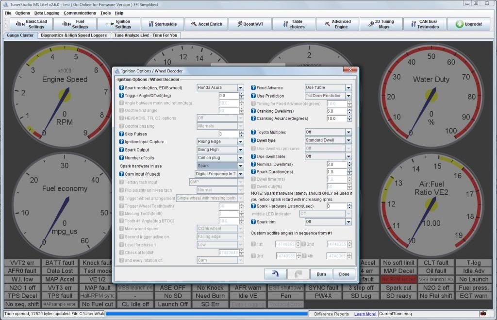
Here's the MS3PRO ignition setup for the OEM Honda/Acura distributor
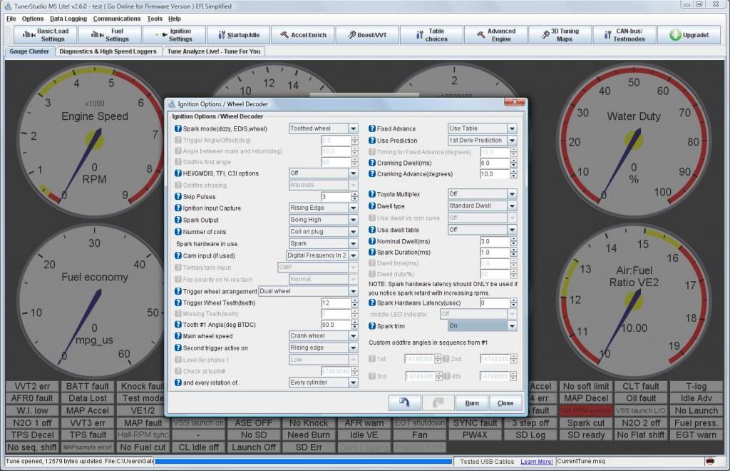
And here's the ignition setup for a dual toothed wheel COP setup
I think I have this setup right so far.
Select Dual Wheel, no missing teeth. Designate the Crank as the main wheel speed, input 12 teeth. All I need to do is figure out what the first tooth angle BTDC is.
The cam input is on Digital Frequency 2, basically the second VR or Hall input. Using the TDC as the secondary wheel I select Every Cylinder, since every time there's a trigger event on that wheel, it's for every cylinder when it reaches TDC
I need to figure out what tooth is considered number 1 on the OEM crank timing belt gear.
Since crankshaft rotation is CCW I'm going to assume that it's the tooth to the left of the TDC mark (duh lol) anyone know how many degrees BTDC that tooth starts? and is Megasquirt considering the angle BTDC where the tooth profile starts to rise or on the flat part of the tooth?
any comments/advice? I tried to make this thread as fluid as possible... thoughts are rolling through my head 1000 miles an hour right now lol
There aren't any real install diagrams as this is a "universal" ECU and flying lead harness (guides are being developed) but since it's based on the MS3X platform I'm using the MS3X honda guide as a rough starting point.
Now, my chassis is OBD2A so I have 4 sensors total, 3 in the distributor and 1 on the crank.
Distributor
CYP - Cylinder Position, 1 tooth. It tracks Cylinder 1 ATDC, something like 45 or 60 degrees ATDC? I don't know exactly
CKP - Crankshaft Position, 24 Teeth
TDC - Top Dead Center, 4 Teeth
Crankshaft
CKF - Crankshaft Fluctuation, 12 Teeth
Images just in case it helps
Distributor
CKF
Now, megasquirt, for direct coil on plug use says you can just use the TDC sensor and ignore everything else. This honestly doesn't make any sense to me because without knowing crankshaft position the ecu cannot determine which tooth on the TDC wheel correlates to what cylinder. unless they were saying use the CKP and TDC... the guide is pretty vague here.
I've also heard of them using the CKP and CYP triggers, you simply have to know at what degree the CYP is oriented to and from what I understand some honda oem distributors have them oriented differently. I've also heard that when people use this combination that they get signal noise from the CKP despite the MS3PRO having signal conditioners on it's VR/Hall inputs. Also using the 24 tooth CKP wheel means that it is effectively a 12 tooth wheel, as there's 2 crank rotations for every 1 cam rotation.
I don't have to use the CKF... The obd2 ecu uses the CKP in the distributor as it's main crankshaft trigger. It simply monitors the CKF to check that timing is "sync'd" between the crank and camshaft and it monitors for any misfires. For emissions purposes I could simply splice the CKP signal to the CKF pins on the ecu and it wouldn't know the difference. However given the CKP noise issue I could easily run the CKF as the ecu's crank reference since I have the needed OEM parts.
So I was planning to use the CKF sensor as the Crank trigger and the TDC sensor as the Cam trigger. MS3PRO only requires these two for timing purposes.
Here's the MS3PRO ignition setup for the OEM Honda/Acura distributor
And here's the ignition setup for a dual toothed wheel COP setup
I think I have this setup right so far.
Select Dual Wheel, no missing teeth. Designate the Crank as the main wheel speed, input 12 teeth. All I need to do is figure out what the first tooth angle BTDC is.
The cam input is on Digital Frequency 2, basically the second VR or Hall input. Using the TDC as the secondary wheel I select Every Cylinder, since every time there's a trigger event on that wheel, it's for every cylinder when it reaches TDC
I need to figure out what tooth is considered number 1 on the OEM crank timing belt gear.
Since crankshaft rotation is CCW I'm going to assume that it's the tooth to the left of the TDC mark (duh lol) anyone know how many degrees BTDC that tooth starts? and is Megasquirt considering the angle BTDC where the tooth profile starts to rise or on the flat part of the tooth?
any comments/advice? I tried to make this thread as fluid as possible... thoughts are rolling through my head 1000 miles an hour right now lol
 04-30-2014, 03:36 AM
#2
04-30-2014, 04:26 AM
#3
Who is Mr Robot?
Thread Starter
iTrader: (2)
Join Date: Jul 2004
Location: ATL - Where the Pimps and Players dwell
Posts: 21,474
Likes: 0
Received 10 Likes
on
10 Posts
and since I know someone is going to say "Why Megasquirt?" here's a feature list.
For 1200 dollars you get the following
Hardware features:
Freescale MC9S12X 16 bit, 50 MHz asymmetrical dual core processor
10 saturated injector drivers
8 logic level ignition outputs
3 high current (5 amp) general purpose outputs - 2 can be reconfigured as additional injector drivers, and all can be used as PWM outputs
3 medium current (3 amp), high frequency general purpose outputs
All unused injector and ignition outputs can be used as spare on/off or other outputs. This ECU has a LOT of I/O!
1 stepper H-bridge driver
Camshaft and crankshaft differential inputs - supports VR, Hall effect, and optical input
12 volt tach output
Fuel pump output
8 analog inputs (5 dedicated sensor inputs, 3 spare/general purpose)
4 spare digital on/off inputs
3 spare digital frequency inputs
2 knock sensor inputs
RS232, USB 2.0, and CAN communication
Onboard 8 gigabyte SD card for internal data logging
Internal ECU temperature sensor
Real time clock
Temperature range: -30 to +80 degrees C (-40 to +85 without battery for real time clock)
Software features:
Supports speed density, alpha-N (TPS based), or MAF based fuel and spark tables
1 microsecond injector pulse width resolution
Tables for nonlinear injector behavior at small pulse widths
Allows blending multiple load types, including specialized mode for independent throttle bodies
Supports a wide variety of OEM cam and crank position sensors
Individual cylinder trim tables for fuel and ignition
Accelerator pump or model based acceleration enrichment
Closed or open loop idle speed control
Closed or open loop boost control with two separate wastegate outputs, and gear or speed based tuning options
On/off or closed loop continuously variable valve timing (VVT) control - supports up to 4 channels
On/off or progressive nitrous control
Traction control by VSS vs Gear Ratio, Perfect Run, Individual Wheel Speed Sensors or RPM
Rally anti-lag with rotational idle
Rotary support - can run up to 4 rotor engines with separate leading and trailing spark tables
Staged injection
Table switching
16 x 16 fuel and spark tables - can be reconfigured to function as 30 x 16 or 16 x 30 by switching tables based on RPM or load
2 or 3 step rev limiter (launch control) with no-lift shifting
Transbrake Control
Speed based launch control
Wideband AFR target tables
Flex fuel sensor input for easy switching between gasoline and E85 - can automatically change fuel, ignition, and boost maps based on ethanol content of gasoline
Knock control with adjustable crank angle windowing can adjust sensitivity based on RPM or which cylinder is firing
Allows repurposing injector or ignition outputs as general purpose outputs, or high current outputs as injector drivers for 12 cylinder sequential applications
Real time barometric correction (external sensor required)
A/C and cooling fan control with idle compensation
Safety shutdown based on AFR or EGT input
Sequential shift cut and air shifter control
Diagnostics to detect and ignore failing sensors - can even automatically switch from speed density to alpha-N in the event of a MAP sensor failure
and things like
A fully end-user configurable CANBus system
Auto tuning of warmup, VE, and fuel tables
Individual cylinder EGT and Wideband O2 sensor support
Supports Air/Fuel command values so the ecu uses real-time wideband feedback to control air fuel ratio
Turbo shaft speed sensor input
High Power Time Enrichment (allows the ecu to richen up AFR using wideband feedback after prolonged high load events to cool piston crown)
Water/Methanol injection system control (injection rate, pump duty cycle, activation point, injection rate ramp up, etc)
Oil pressure monitoring and shut down option if oil pressure drops below user selected value
GPS Support - will take an external 10khz GPS Sensor and display true speed, distance travelled, outline race track diagram and display lap times and much more.
3 axis accelerometer support
wifi and bluetooth support - will allow iphone or android users to datalog, display the digital dash, and tune from their device
Fuel Economy monitor and Torque/HP monitor (allows you to display these values on the digital dash and datalog them)
Multiple VE tables
Short term and long term fuel trims
Numerous fuel and ignition corrections for everything from fuel pressure and fuel temp, to fuel puddling in the intake manifold, fuel sticking to and leaving the intake walls
Numerous ignition retard features
High speed logger for composite, sync error, tooth, and trigger. allows you to monitor these signals in real time to see if there's an issue with a given sensor.
It will even control alternator output, torque converter lockup, control an automatic trans directly from the ecu (try that aem lol) and it has an automatic tuning method for ITB cars
and much, much more.
Plus an 8ft flying lead wiring harness.
For the money you can't beat its features. it's all standard, nothing extra to pay for to unlock and use
04-30-2014, 05:11 AM
#4

Wont using the cyp and ckp together be better? By using the tdc and ckp youre not telling megasquirt where cylinder one is. Instead its always gonna say a cylinder is hitting. The cyp will tell megasquirt "heres cylinder one, in 6 ckp ticks cylinder 3 will hit" and so on.
Sorry I cant help you with the crank timing gear degree. I always thought it was a tdc exact.
Oops kind of a derp moment. Megasquirt doesnt need to exactly know what cylinder is hitting unless youre doing a sequential fire injection. Im assuming youre gonna batch fire it since youre gonna have it pulse every cylinder. (The rotor will just hit on any cylinder its pointing to, thats what I forgot to picture in my head)
Btw, I love megasquirt. I was gonna ms2 my 280z one day but that plan is never gonna happen seeing as I dont own that car anymore
I read your post again. Youre goin coil on plug. I dont the tdc would be a good idea because with cop you don't have the rotor deciding where the spark goes. Megasquirt will need to know cylinder 1 position to know when to fire.
Even if you used the ckf to find the crank, the tdc with its 4 teeth are gonna make it hard for ms to find cylinder 1. I think theyre telling you to use the cyp. The ckp will give you better resolution for ignition timing I would think vs the ckf
Sorry if my post is all over thebplace and possibly not helpful. I havent messed with megasquirt or the triggering system on hondas. I did notice when I was testing a distributor uninstalled (to make sure my obd1/obd0 splices were right) the ecu wasnt triggering any spark till after it went around and eas triggered by the cyp.
Last edited by m4xwellmurd3r; 04-30-2014 at 05:38 AM.
04-30-2014, 05:57 AM
#5
Who is Mr Robot?
Thread Starter
iTrader: (2)
Join Date: Jul 2004
Location: ATL - Where the Pimps and Players dwell
Posts: 21,474
Likes: 0
Received 10 Likes
on
10 Posts
By megasquirt asking where tooth one is on the crank wheel it can then determine phasing from there. as after that point every time a cam signal is received the ecu knows which cylinder to fire because the ecu is being told that every time the tdc sensor reads a tooth it should fire x cylinder.
Let's say tooth one is 60* btdc. so after the ecu knows offset before tdc and number of teeth on the main wheel it uses these two to determine how many degrees each tooth equals. the ecu know it's a 4cyl so based on the tdc signal vs crank signal it knows which cylinder to fire (there's also a way to set every cylinders tdc timing but I can't figure out how to unlock it lol) after you set tooth one offset you have to adjust the distributor timing until the timing light matches the sync value displayed by megasquirt. so now based off of the offset of tooth one, the sync timing value, and the ecu knowing every cam signal equals tdc for every signal it can then properly time spark and fuel events
Although I'm wondering if the crank wheel doesn't have a missing tooth then what would the ecu use to determine which tooth is number one?
at least that's how it should work.
using the ckp or ckf doesn't matter. the 24 teeth on the cpk translates to 12 teeth per crank revolution (the same as the ckf) since every crank revolution is half a cam revolution (24/2=12)
Plus others using the ckp have had problems with signal noise causing misfires, erratic timing, sync errors, etc.
I'm running full sequential. you get much better low load performance that way. this isn't a drag car so I need good low load drivability
luckily diyautotune is right down the street so I might go talk to the braintrust about this.. since the developer of the ms3pro and tuner studio all work there. if they can't figure it out it can't be done.
04-30-2014, 06:08 AM
#6
But the crank wheel still only has 12 evenly spaced teeth. There is no "one" mark on them. Every 6 teeth is 1 tdc tooth on the cam. So ms will only know every 6 teeth is one cylinder, but it still wont know which cylinder. Thats why trigger wheels usually have a missing tooth when you run megasquirt. The missing one is for tdc cylinder 1.
If you use the cyp and ckf, the engine will crank, then cyp will trigger, telling ms its at tdc cylinder 1. From there it will know 6 teeth is cylinder 3, 6 more is 2, more is 4, then the cyp comes back around and it restarts the trigger count.
Regardless of what combo you use you need to have a single tooth that indicates where tdc cylinder 1 is.
Hondas use the cyp to get tdc. I think it uses the tdc for injector siginaling, and the ckp for timing.
Like I said, without a single tooth indicating tdc 1, it doesnt matter what degree you say it is, megasquirt wont know where it is.
Youre right thouvh, using the ckp or ckf doesnt matter. The ckf spins twice for 24 triggers for every one rotation of the 24 tooth ckp.
You need to use the cyp and either the ckf or ckp. But not the tdc wheel. The tdc wheel will screw things up
04-30-2014, 06:11 AM
#7
Who is Mr Robot?
Thread Starter
iTrader: (2)
Join Date: Jul 2004
Location: ATL - Where the Pimps and Players dwell
Posts: 21,474
Likes: 0
Received 10 Likes
on
10 Posts
There's a tdc line on the ckf crank gear. the tooth before it would be considered number one. megasquirt works on wheels that aren't missing tooth style. maybe I'm just to stupid to set it up lol. Granted I could put the OEM ckf gear in the mill and knock the first tooth off.
the problem is determining the timing of the cyp in relation to the crank and tdc triggers
the problem is determining the timing of the cyp in relation to the crank and tdc triggers
Trending Topics
04-30-2014, 06:20 AM
#8
There's a tdc line on the ckf crank gear. the tooth before it would be considered number one. megasquirt works on wheels that aren't missing tooth style. maybe I'm just to stupid to set it up lol. Granted I could put the OEM ckf gear in the mill and knock the first tooth off.
the problem is determining the timing of the cyp in relation to the crank and tdc triggers
the problem is determining the timing of the cyp in relation to the crank and tdc triggers
I think if you hooked on a timing wheel you could degree the cyp to figure out its relation to the ckf. All ypu really need to know is that once cyp triggers once, you have 180� on the ckf before cylinder 3 hits. That'll be 6 teeth. The cyp and A tooth on the ckf will hit at the same time if you set the distributor to 0 degrees
04-30-2014, 06:22 AM
#9
Who is Mr Robot?
Thread Starter
iTrader: (2)
Join Date: Jul 2004
Location: ATL - Where the Pimps and Players dwell
Posts: 21,474
Likes: 0
Received 10 Likes
on
10 Posts
But see even megasquirt says ignore the cyp, use tdc because the degree values for all 4 flats are constant.
04-30-2014, 06:27 AM
#10
By using cop you are required to have a single tooth triggering tdc1. Same with sequential fired injection
(I just looked at their site. They say to ignore both sensors and just use the tdc, which works great if youre using the stock ignition setup of a distributor and single coil)
04-30-2014, 06:30 AM
#11
Who is Mr Robot?
Thread Starter
iTrader: (2)
Join Date: Jul 2004
Location: ATL - Where the Pimps and Players dwell
Posts: 21,474
Likes: 0
Received 10 Likes
on
10 Posts
bleh, if I'm going to the point of running something like a 36-1 crank trigger then I'll eliminate the distributor entirely.
I can make a longer sensor mount bracket so I can run a T1 style cam trigger over my Endyn secondary tensioner.
A little more work when swapping back to obd2 for emissions but since my harness is using amphenol connectors I can hot swap the oem harness in place in only a few minutes
Sometimes I wish it was obd1 so I didn't have to deal with this **** but I just can't get used to the look of the 92-95 civics :/
04-30-2014, 06:35 AM
#12
Yeah, from the sounds of it youre gonna have to do somethung like thay because with your cop and sequential injection you absolutely need a dedicated cyl 1 tdc trigger. Be it a missing tooth or extra sensor
04-30-2014, 06:35 AM
#13
Who is Mr Robot?
Thread Starter
iTrader: (2)
Join Date: Jul 2004
Location: ATL - Where the Pimps and Players dwell
Posts: 21,474
Likes: 0
Received 10 Likes
on
10 Posts
although with the 36-1 crank wheel I guess technically I wouldn't need a cam wheel
04-30-2014, 06:39 AM
#14
Who is Mr Robot?
Thread Starter
iTrader: (2)
Join Date: Jul 2004
Location: ATL - Where the Pimps and Players dwell
Posts: 21,474
Likes: 0
Received 10 Likes
on
10 Posts
derp, to go fully sequential with the missing tooth wheel I need a cam trigger.
04-30-2014, 06:45 AM
#15
04-30-2014, 06:48 AM
#16
Who is Mr Robot?
Thread Starter
iTrader: (2)
Join Date: Jul 2004
Location: ATL - Where the Pimps and Players dwell
Posts: 21,474
Likes: 0
Received 10 Likes
on
10 Posts
AHAH
I don't know how I missed this in the manual.
magic table of crank/cam triggers
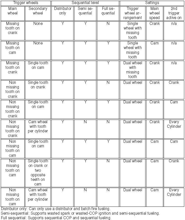
so I can use the CKF and the CYP and be fine.
I don't know how I missed this in the manual.
magic table of crank/cam triggers
so I can use the CKF and the CYP and be fine.
04-30-2014, 06:49 AM
#17
Who is Mr Robot?
Thread Starter
iTrader: (2)
Join Date: Jul 2004
Location: ATL - Where the Pimps and Players dwell
Posts: 21,474
Likes: 0
Received 10 Likes
on
10 Posts
It would be hard... the smallest 36-1 wheel offered is 4" combine that with a hall effect sensor and you see that the stock distributor casing isn't big enough.
04-30-2014, 06:54 AM
#18
Make one! Lol or use the ckp and break a tooth off. Itll be a tooth ever 15 vs every 10 but I bet it would work
04-30-2014, 01:53 PM
#19
Who is Mr Robot?
Thread Starter
iTrader: (2)
Join Date: Jul 2004
Location: ATL - Where the Pimps and Players dwell
Posts: 21,474
Likes: 0
Received 10 Likes
on
10 Posts
Hmm, I wonder if I could remove a tooth off the ckp... the trick would be to get it exactly at tdc, assuming it has it's own tooth. my only fear is I'd have signal noise using the ckp like pretty much everyone has.
I could press it off but lining it back up on the shaft would be a bitch since it doesn't have any sort of indexing.
I could press it off but lining it back up on the shaft would be a bitch since it doesn't have any sort of indexing.
04-30-2014, 08:56 PM
#20
Yeah, im sure one tooth points to tdc exact, but youre right, it would be tricky. Its too bad our cars dont have an optical sensor like z cars have
http://www.diyautotune.com/catalog/5...d8269935330e6c
http://www.diyautotune.com/catalog/5...d8269935330e6c
05-01-2014, 12:22 AM
#21
Who is Mr Robot?
Thread Starter
iTrader: (2)
Join Date: Jul 2004
Location: ATL - Where the Pimps and Players dwell
Posts: 21,474
Likes: 0
Received 10 Likes
on
10 Posts
I have a few optical sensors off of my sr20dets and vg30dett laying around.
however given the CAS design and the fact it spins the wrong way it would be hard to make it work
however given the CAS design and the fact it spins the wrong way it would be hard to make it work
05-01-2014, 01:04 AM
#23
Who is Mr Robot?
Thread Starter
iTrader: (2)
Join Date: Jul 2004
Location: ATL - Where the Pimps and Players dwell
Posts: 21,474
Likes: 0
Received 10 Likes
on
10 Posts
it is. trust me
and the CAS itself is roughly 4 inches long. it would require machining down the housing, machining a shorter shaft or some sort of key system to work with a honda cam and then you have the sensor itself, which is actually 2 optical sensors, a 360 degree ring for crank timing with an endless amount of teeth and a 4 hole inner wheel for each cylinders tdc, and from 1-4 each hole gets longer
and the CAS itself is roughly 4 inches long. it would require machining down the housing, machining a shorter shaft or some sort of key system to work with a honda cam and then you have the sensor itself, which is actually 2 optical sensors, a 360 degree ring for crank timing with an endless amount of teeth and a 4 hole inner wheel for each cylinders tdc, and from 1-4 each hole gets longer
05-01-2014, 01:10 AM
#24
Who is Mr Robot?
Thread Starter
iTrader: (2)
Join Date: Jul 2004
Location: ATL - Where the Pimps and Players dwell
Posts: 21,474
Likes: 0
Received 10 Likes
on
10 Posts
but now I've gone even crazier.
I've always wanted to do a carpc and a digital dash display... and i've decided to do it. that way tunerstudio will display all pertinent info on a 10.2" diagonal (8.8in x 5.1in) 16:9 widescreen led touchscreen monitor in place of the gauge cluster (perfect fit)
and then a 10.4 4:# monitor in place of the headunit and climate controls. Since i won't have ac, only heat, I will either use my 99-00 digital airbox stuff and let the pc trigger a Fusion Brain V6 that will then control a dc motor for temp (control the heater flow valve) as well as a relay bank to trigger each vent coniguration. as well as controlling all of the lighting, windows, locks, cameras (for when I get pulled over lol) etc
it will also be bluetoothed, gps'd, and 3 axis accelerometer'd on top of being connected to ATT 4G LTE network for internet radio (pandora) and whatever else I want as well as an integrated phone system
badass fully digital car for 1,000 dollars? Methinksyes
at least this way I can monitor the ecu datastream conveniently in real time, all the time, without having a stupid laptop taking up space and sliding everywhere
05-01-2014, 07:03 PM
#25
it is. trust me
and the CAS itself is roughly 4 inches long. it would require machining down the housing, machining a shorter shaft or some sort of key system to work with a honda cam and then you have the sensor itself, which is actually 2 optical sensors, a 360 degree ring for crank timing with an endless amount of teeth and a 4 hole inner wheel for each cylinders tdc, and from 1-4 each hole gets longer
and the CAS itself is roughly 4 inches long. it would require machining down the housing, machining a shorter shaft or some sort of key system to work with a honda cam and then you have the sensor itself, which is actually 2 optical sensors, a 360 degree ring for crank timing with an endless amount of teeth and a 4 hole inner wheel for each cylinders tdc, and from 1-4 each hole gets longer