
Injector wiring / IACV Issues ** Please help me out.
 07-05-2005, 02:52 PM
#1
Honda-Tech Member
Thread Starter
Join Date: Jun 2003
Location: Cincinnati, OH, USA
Posts: 1,722
Likes: 0
Received 0 Likes
on
0 Posts
I am not really sure where to start. I would first like to start off by saying, Hondata was more than useless in helping with this issue. I really feel sorry for those of you that need/have tried to get help from them. Rather than help, they spend all the time on the phone explaining how you are obviously wrong, rather than trying to listen to the problem at hand.
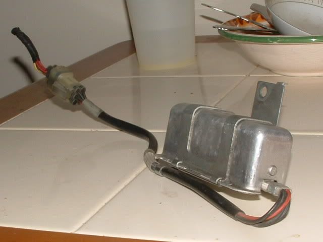
First off, here is a picture of my wiring. I know it is sloppy, but I have swapped it around 3-4 times. i will redo it after it is correct and my issues are resolved.

I have wired the injectors according to 2 different schematics. First: Hondatas tech schematic. Second: TurboGixxers schematic. I first found the continuity between the 4 injectors and the butt connector. I then snipped the wires. I wired the 12v side (4 wires) into the red wire on the resistor pack, then wired the remaining 4 individually into the remaining 4 yellow/brown injector wires.
Here is where my dillema starts. I have had a few people look at the wiring and they have all said it was correct. So now, I turn it over to you all. Assuming the wiring is correct, I am not sure where the issue comes to play. My IACV pops on and stays on when ignition is applied. (12v or engine running)
You can hear the plunger pop and humm constantly. If I remve the butted connector from the injector clip as shown below, the buzzing stops.

So I was puzzled. I called AEM and was told the circuit boards are completely different between the injectors and the IACV in the AEM EMS unit. They also insisted the wiring was the issue. This led me to test another EMS, which yielded the same results. Puzzled, I then tried an OEM ECU... Same issue. At this point, I had to beleive it was the wiring. So, I began to tinker. Only one of the 4 wires from th eactual butted connector contains 12v supply. There is continuity between the butt connector and the IACV at the lower right pin on the above picture. How can this be, considering AEM said these are different circuits all together? Unless, I have wired incorrectly, which brings me right back in a full circle. I am sincerely frustrated and keep receivng the same answers over and over. I have searched and read posts for over a week now. I have tried to edit the ems to adjust the HZ of the IACV, with no change in resolve.
Here is the real kicker, The car ran just fine with no problems before I cut the wiring harness to wire in the resistor box. The ems was in th ecar and no issues with either the IACV or the injectors existed. I have also tried to switch out IACV thinking this could be the issue...Yep, you guessed it, no resolve.
I am truly open to advice, suggestions, and constructive criticism; however, please do not patronise me, I am frustrated and really do not have the patience for it.
Thanks in advance for all your help!
Modified by Si Integra at 1:22 AM 7/6/2005
First off, here is a picture of my wiring. I know it is sloppy, but I have swapped it around 3-4 times. i will redo it after it is correct and my issues are resolved.
I have wired the injectors according to 2 different schematics. First: Hondatas tech schematic. Second: TurboGixxers schematic. I first found the continuity between the 4 injectors and the butt connector. I then snipped the wires. I wired the 12v side (4 wires) into the red wire on the resistor pack, then wired the remaining 4 individually into the remaining 4 yellow/brown injector wires.
Here is where my dillema starts. I have had a few people look at the wiring and they have all said it was correct. So now, I turn it over to you all. Assuming the wiring is correct, I am not sure where the issue comes to play. My IACV pops on and stays on when ignition is applied. (12v or engine running)
You can hear the plunger pop and humm constantly. If I remve the butted connector from the injector clip as shown below, the buzzing stops.
So I was puzzled. I called AEM and was told the circuit boards are completely different between the injectors and the IACV in the AEM EMS unit. They also insisted the wiring was the issue. This led me to test another EMS, which yielded the same results. Puzzled, I then tried an OEM ECU... Same issue. At this point, I had to beleive it was the wiring. So, I began to tinker. Only one of the 4 wires from th eactual butted connector contains 12v supply. There is continuity between the butt connector and the IACV at the lower right pin on the above picture. How can this be, considering AEM said these are different circuits all together? Unless, I have wired incorrectly, which brings me right back in a full circle. I am sincerely frustrated and keep receivng the same answers over and over. I have searched and read posts for over a week now. I have tried to edit the ems to adjust the HZ of the IACV, with no change in resolve.
Here is the real kicker, The car ran just fine with no problems before I cut the wiring harness to wire in the resistor box. The ems was in th ecar and no issues with either the IACV or the injectors existed. I have also tried to switch out IACV thinking this could be the issue...Yep, you guessed it, no resolve.
I am truly open to advice, suggestions, and constructive criticism; however, please do not patronise me, I am frustrated and really do not have the patience for it.
Thanks in advance for all your help!
Modified by Si Integra at 1:22 AM 7/6/2005
 07-05-2005, 03:42 PM
#2
Junior Member
Join Date: Aug 2001
Location: Vancouver, BC, Canada
Posts: 653
Likes: 0
Received 0 Likes
on
0 Posts
single wire from the resistor box should face the ecu
the 4 single wires should be on the injectors side
what motor and ecu do you have ??
y7s have a weird iacv that have to be rewired for obd1
also does aem ems have icv duty cycle adjustment ??
the 4 single wires should be on the injectors side
what motor and ecu do you have ??
y7s have a weird iacv that have to be rewired for obd1
also does aem ems have icv duty cycle adjustment ??
07-05-2005, 03:51 PM
#3
Honda-Tech Member
Join Date: Apr 2004
Location: NoVa, usa
Posts: 1,480
Likes: 0
Received 0 Likes
on
0 Posts
Step 8: Installing Injector Resistor Box<p>--> Some obd0 Honda's and some other cars use low impedance injectors which need a resistor box. You can find these at a junk yard or for cheap on ebay.
 <p>--> On obd1 Honda's, there is a "dead end" clip on the wiring harness in the right corner of the engine bay. (obd2 has this clip under the intake manifold). This clip has the electrical power running through it that goes to the injectors. It is right next to the clutch master cylinder.<p>
When you find the clip, pop off the Protecting cover so it exposes the inside.<p>--> Using a multimeter, check for conductivity between each clip and the end's of the "dead-end" connector. The idea is to find which wires actually are routed to the injector clips, so seeing if electricity can flow, you can guess-and-check and find out.
There are eight different wires going into the "dead-end" connector, all of which you must check to see if they are the winners! According to h-t, it could be random placed, so do not assume and follow my example. CHECK FOR YOURSELF TO MAKE SURE!

The red dots are showing which ones came out conductive for me. AGAIN, CHECK FOR YOURSELF TO MAKE SURE!<p>--> Once you found out which ones are conductive, move down 2-4 inches and cut the wire. This break in to wire is where you will have your resistor tie into the system. Strip both sides of the new striped wires.<p>--> If you take a look at your resistor box, there should be 5 wires coming out of it. Four of them should be common color and one of them should be a different color. Strip all the ends if they are not already.
 <p>--> Next, Take the Single different color wire from the resistor box and solder it to all Four of the wires on the "dead-end" side. See diagram for better explaintion.
 <p>Connect Each one of the Four common color wires from the resistor box to one of the four yellow/black wires on the Injector side of the cut. Solder each wire seperately, no order is nessecary.
 <p>Here is a Diagram I made for better explaintion.
 <p>--> Wrap all the exposed wires up with electrical tape and mount the resistor box in the corner. here is the finished product.

<p>--> On obd1 Honda's, there is a "dead end" clip on the wiring harness in the right corner of the engine bay. (obd2 has this clip under the intake manifold). This clip has the electrical power running through it that goes to the injectors. It is right next to the clutch master cylinder.<p>When you find the clip, pop off the Protecting cover so it exposes the inside.<p>--> Using a multimeter, check for conductivity between each clip and the end's of the "dead-end" connector. The idea is to find which wires actually are routed to the injector clips, so seeing if electricity can flow, you can guess-and-check and find out.
There are eight different wires going into the "dead-end" connector, all of which you must check to see if they are the winners! According to h-t, it could be random placed, so do not assume and follow my example. CHECK FOR YOURSELF TO MAKE SURE!
The red dots are showing which ones came out conductive for me. AGAIN, CHECK FOR YOURSELF TO MAKE SURE!<p>--> Once you found out which ones are conductive, move down 2-4 inches and cut the wire. This break in to wire is where you will have your resistor tie into the system. Strip both sides of the new striped wires.<p>--> If you take a look at your resistor box, there should be 5 wires coming out of it. Four of them should be common color and one of them should be a different color. Strip all the ends if they are not already.
<p>--> Next, Take the Single different color wire from the resistor box and solder it to all Four of the wires on the "dead-end" side. See diagram for better explaintion.<p>Connect Each one of the Four common color wires from the resistor box to one of the four yellow/black wires on the Injector side of the cut. Solder each wire seperately, no order is nessecary.<p>Here is a Diagram I made for better explaintion.<p>--> Wrap all the exposed wires up with electrical tape and mount the resistor box in the corner. here is the finished product.
07-05-2005, 05:08 PM
#4
Honda-Tech Member
Thread Starter
Join Date: Jun 2003
Location: Cincinnati, OH, USA
Posts: 1,722
Likes: 0
Received 0 Likes
on
0 Posts
That is how I have it wired.
Please do not be misled by the opposing colors. I used a resistor pack from a later model accord. It flips the colors of the injector wires/power wires.
The motor is an LS b18b (obviously modified)
The y7 does have iacv issues? Perhaps the dc b18b does as well...
As stated above, the ems does allow for manipulation of the iac duty cycle. I have tried to run it in several different formats.
Thanks for the posts, please keep them coming.

Thread
Thread Starter
Forum
Replies
Last Post