

Help with Compressor Map

Thread Starter
Honda-Tech Member
Joined: Apr 2010
Posts: 407
Likes: 1
I just plotted map points for the turbo I am planning on using and would like to get some feedback on my findings.
This is the first time I have ever done this and as such, I am uncertain about what conclusions can be drawn.
The engine in discussion is an F22B1 with delta 260 cam, ported intake manifold, h22 tb, and the turbo is a turbonetics t3/to4e 50 trim, yet to be installed of course.
I have an s300 I will be using for engine management and as such plan on raising the rev limiter to 6600 if power accords it.
I also used 6600 as the max engine RPM in my calculations.
For reference:
Pressure Ratio=1.81@ 12psi
Max CFM=440.7@12psi
I have plotted three points per the FAQ article, 100%, 75% and 50% throttle.
Those points are numbered:
1=100%
2=75%
3=50%
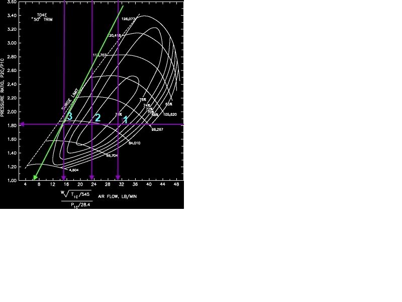
I am also unclear if I plotted the surge line correctly.
It is the single green line which does cross the maps surge limit at higher PR's.
What are the ramifications of this?
How suitable is this for my application?
Again this is the first go-round on this type of thing for me so useful information is extremely appreciated.
This is the first time I have ever done this and as such, I am uncertain about what conclusions can be drawn.
The engine in discussion is an F22B1 with delta 260 cam, ported intake manifold, h22 tb, and the turbo is a turbonetics t3/to4e 50 trim, yet to be installed of course.
I have an s300 I will be using for engine management and as such plan on raising the rev limiter to 6600 if power accords it.
I also used 6600 as the max engine RPM in my calculations.
For reference:
Pressure Ratio=1.81@ 12psi
Max CFM=440.7@12psi
I have plotted three points per the FAQ article, 100%, 75% and 50% throttle.
Those points are numbered:
1=100%
2=75%
3=50%
I am also unclear if I plotted the surge line correctly.
It is the single green line which does cross the maps surge limit at higher PR's.
What are the ramifications of this?
How suitable is this for my application?
Again this is the first go-round on this type of thing for me so useful information is extremely appreciated.
Thread Starter
Honda-Tech Member
Joined: Apr 2010
Posts: 407
Likes: 1
After looking at some plotted charts I found I should have ended my surge line at my #3 plotted point and not extended it past that point.
That takes care of the surge issue.
Still looking for some general information about the rest.
That takes care of the surge issue.
Still looking for some general information about the rest.
Thread Starter
Honda-Tech Member
Joined: Apr 2010
Posts: 407
Likes: 1
I understand the center island represents the highest levels of efficiency but I have yet to find a compressor that will plot all three points within that area.
The issue seems kind of inherent to the changing airflow as the engine rpm changes.
Do you have any suggestions as far as a more effecient compressor for my application.
The issue seems kind of inherent to the changing airflow as the engine rpm changes.
Do you have any suggestions as far as a more effecient compressor for my application.
Thread Starter
Honda-Tech Member
Joined: Apr 2010
Posts: 407
Likes: 1
I gotta say, I'm stunned, after all the reading and parts accumulation I've done toward my build I come with this question and after 200+ views can hardly get an intelligent response.
I've seen noobs make absurd threads that gather amazing attention, then I ask about a compressor map and suddenly no one has anything to say?
I've seen noobs make absurd threads that gather amazing attention, then I ask about a compressor map and suddenly no one has anything to say?
hmm.. let me take a stab..
im not familiar with the turbo.. is it a 48 or 63 hotside?
I wouldnt do 3 throttle positions.. I would concentrate on the full throttle, and try to target the efficiency range, the other throttle positions should fall in line after you target your efficiency range.
Whats the specs on the turbo?
Ill check out the map
Thread Starter
Honda-Tech Member
Joined: Apr 2010
Posts: 407
Likes: 1
I am 95% sure it is a .63 but I have to double check the next time I am at my garage.
All of the points plotted do represent WOT airflow.
The points are moving depending on changing engine RPM, therefore the points move to the right on the graph as RPM and consequently airflow with it increase.
All of the points plotted do represent WOT airflow.
The points are moving depending on changing engine RPM, therefore the points move to the right on the graph as RPM and consequently airflow with it increase.

I'll simply say this. You're using the wrong parameters to determine cfm flow relative to your PR. you need to go by multiple rpm points relative to the PR to determine what efficiency your engine demand flow will be on the island. BTW you'll never get the rpm range to stay within the highest efficiency at all points because it is not physically or mathematically possible.
I won't go into more of the math and configuration, as it took me a very long time to master and won't just give that away; you gotta earn your stripes first. But you won't get them all in one part of th island based on throttle %. It doesn't work that way
I won't go into more of the math and configuration, as it took me a very long time to master and won't just give that away; you gotta earn your stripes first. But you won't get them all in one part of th island based on throttle %. It doesn't work that way
Trending Topics
Thread Starter
Honda-Tech Member
Joined: Apr 2010
Posts: 407
Likes: 1
I'll simply say this. You're using the wrong parameters to determine cfm flow relative to your PR. you need to go by multiple rpm points relative to the PR to determine what efficiency your engine demand flow will be on the island. BTW you'll never get the rpm range to stay within the highest efficiency at all points because it is not physically or mathematically possible.
I won't go into more of the math and configuration, as it took me a very long time to master and won't just give that away; you gotta earn your stripes first. But you won't get them all in one part of th island based on throttle %. It doesn't work that way
I won't go into more of the math and configuration, as it took me a very long time to master and won't just give that away; you gotta earn your stripes first. But you won't get them all in one part of th island based on throttle %. It doesn't work that way
What I am taking from your post is there are more, or different factors going on at different speeds that my calculations aren't reflecting, is that right?
I also didn't expect all the points to fall within the highest levels of compressor efficiency, but rather just wanted to know how the best arrangements, compressors matched to ideal engines, would appear on a map for comparison sake.
Should my PR always stay constant as well, is there ever a situation where it would change?
I am trying to learn and realize this is the sort of information gained through experience of seeing these things through.
What I am taking from your post is there are more, or different factors going on at different speeds that my calculations aren't reflecting, is that right?
I also didn't expect all the points to fall within the highest levels of compressor efficiency, but rather just wanted to know how the best arrangements, compressors matched to ideal engines, would appear on a map for comparison sake.
Should my PR always stay constant as well, is there ever a situation where it would change?
Last edited by TheShodan; May 12, 2012 at 06:45 PM.

Thread
Thread Starter
Forum
Replies
Last Post
mrx
Forced Induction
5
Dec 3, 2004 05:41 PM
eddyboy
Forced Induction
5
Sep 13, 2004 12:58 PM