When you click on links to various merchants on this site and make a purchase, this can result in this site earning a commission. Affiliate programs and affiliations include, but are not limited to, the eBay Partner Network.
So I'm finishing putting this build together and would appreciate some pointers with reference to the boost controller set up and vacuum lines. Basically It's a forged K20a2 in a civic EP3. Running Sheepy twin scroll manifold with 2 wastegates.
My engine builder connected the bottom connectors to the wastegate and said to run both through T or Y piece then to the 3 port solenoid, then connect the other side of the solenoid to the pressure point closest to the turbo. There's no pressure point on the turbo (Garrett GTX3076r Gen2), so had a push tail alloy piece welded to the piping that connects to the turbo. I'm guessing he was referring to using single port, single solenoid method.
My question, is that I've seen other people run a different boost controller setup where the bottom connector is connected to pressure source and the top connector is connected to the pressure source going through the solenoid. Which of the those would be better choice for a 2 wastegates setup?
Running Skunk2 Ultra intake, 3 vacuum connectors, one used for the brake booster, smallest one for FPR only and 3rd one shared between BOV and boost gauge!
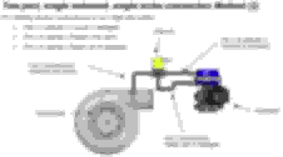
The middle diagram above is the only universally accepted method of connecting a 3-port electronic boost control solenoid. You can get the reference signal from the compressor housing ("pressure only source" in your diagram) OR from the intake manifold. For TWO waste gates, you will simply "Y" the hoses in this diagram for each lower and upper port on the waste gates themselves.
The middle diagram above is the only universally accepted method of connecting a 3-port electronic boost control solenoid. You can get the reference signal from the compressor housing ("pressure only source" in your diagram) OR from the intake manifold. For TWO waste gates, you will simply "Y" the hoses in this diagram for each lower and upper port on the waste gates themselves.
The only advantage of connecting to the intake manifold is that there isn't a boost offset between your reference signal and the value observed by the map sensor. This becomes more prevalent at high boost levels on big turbos or if you have high pressure drop in the system.
So i use the middle diagram, I need to T or Y from the pressure point to second wastegate, so that both wastegates are seeing pressure at the bottom.
At the same time T or Y from post solenoid to the top of both wastegates?
Originally Posted by blitzman
So I'm finishing putting this build together and would appreciate some pointers with reference to the boost controller set up and vacuum lines. Basically It's a forged K20a2 in a civic EP3. Running Sheepy twin scroll manifold with 2 wastegates.
My engine builder connected the bottom connectors to the wastegate and said to run both through T or Y piece then to the 3 port solenoid, then connect the other side of the solenoid to the pressure point closest to the turbo. There's no pressure point on the turbo (Garrett GTX3076r Gen2), so had a push tail alloy piece welded to the piping that connects to the turbo. I'm guessing he was referring to using single port, single solenoid method.
My question, is that I've seen other people run a different boost controller setup where the bottom connector is connected to pressure source and the top connector is connected to the pressure source going through the solenoid. Which of the those would be better choice for a 2 wastegates setup?
Running Skunk2 Ultra intake, 3 vacuum connectors, one used for the brake booster, smallest one for FPR only and 3rd one shared between BOV and boost gauge!
You need to plug it. If you bought the WG new, I would think it should have come with a plug. I have an MV-S and it came with plugs for the open ports.
You need to plug it. If you bought the WG new, I would think it should have come with a plug. I have an MV-S and it came with plugs for the open ports.
If you're running BBG or other form of EBC, you'll be using the 2 ports you have nippled now and all others, except the water ports, need to be closed or you'll never see boost above gate pressure. I just discovered this yesterday. Lol! If you're running a standard MBC, you'll be using the bottom port you got the nipple in and the other 2 bottom ports plugged; top 2 can be left open to atmosphere.