
benefit of exhaust transition after turbo?? looking for some technical data.
 12-03-2006, 03:25 PM
#1
Honda-Tech Member
Thread Starter
Join Date: Jan 2003
Location: the backwoods, usa
Posts: 2,841
Likes: 0
Received 0 Likes
on
0 Posts
i did some searching online as well as on here and couldnt really find anything pertaining directly to turbocharged applications.
i am looking for some technical data as to why doing this is beneficial. so if anyone has anything to share or would like to comment on the matter please feel free to do so.
i attached some pictures below of the application i am using this in. this is for a FSAE project. we are turbocharging a F4i 600cc engine and i have chose to set the exhaust up like this.
here is a shot of the housing.
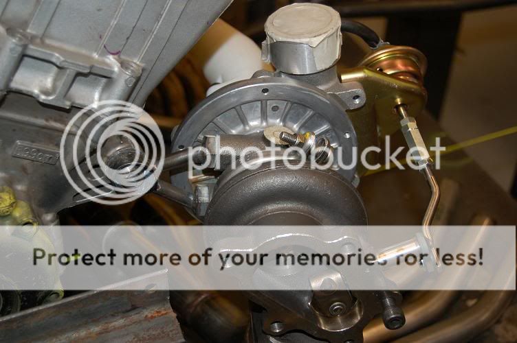
so i milled the flange like this. yes the wastage flapper will be able to open without hitting the flange.

i need to do some slight relief work in the turbine housing and then the transistion will slip through the flange down to the wheel(where the casting edge is, not physically to the wheel). in doing this i am trying to maintain smooth exhaust flow off the turbine wheel and it will block the wastegate off from this tube preventing turbulence when it opens. then i will make a seperate tube for the wastegate and either vent it atmosphere(if it meets noise requirements) or enter it back into the exhaust stream.

the transistion is from 1 5/8" to 2.25". i wanted to run a larger exhaust tube than 1.63" but didnt want to just take a larger tube and crush it oblong to fit on the flange and then patch a section onto the tube to cover the wastegate.
right now i would explain it as:
as little backpressure as possible after the turbo is ideal and since the volume is larger after the transistion the pressure is less.
so lets hear your explainations and reasoning. i'm sure there will be some good information that arises and more than one person will learn something from the responses. lets try to keep this educational and not have the typical honda-tech replies of "thats stupid, youre dumb,etc". if you want to make a smartass comment, please take a deep breath, refrain, and backclick and move on to a different thread. thank you.
Modified by lohatch at 6:10 PM 12/3/2006
i am looking for some technical data as to why doing this is beneficial. so if anyone has anything to share or would like to comment on the matter please feel free to do so.
i attached some pictures below of the application i am using this in. this is for a FSAE project. we are turbocharging a F4i 600cc engine and i have chose to set the exhaust up like this.
here is a shot of the housing.
so i milled the flange like this. yes the wastage flapper will be able to open without hitting the flange.
i need to do some slight relief work in the turbine housing and then the transistion will slip through the flange down to the wheel(where the casting edge is, not physically to the wheel). in doing this i am trying to maintain smooth exhaust flow off the turbine wheel and it will block the wastegate off from this tube preventing turbulence when it opens. then i will make a seperate tube for the wastegate and either vent it atmosphere(if it meets noise requirements) or enter it back into the exhaust stream.
the transistion is from 1 5/8" to 2.25". i wanted to run a larger exhaust tube than 1.63" but didnt want to just take a larger tube and crush it oblong to fit on the flange and then patch a section onto the tube to cover the wastegate.
right now i would explain it as:
as little backpressure as possible after the turbo is ideal and since the volume is larger after the transistion the pressure is less.
so lets hear your explainations and reasoning. i'm sure there will be some good information that arises and more than one person will learn something from the responses. lets try to keep this educational and not have the typical honda-tech replies of "thats stupid, youre dumb,etc". if you want to make a smartass comment, please take a deep breath, refrain, and backclick and move on to a different thread. thank you.
Modified by lohatch at 6:10 PM 12/3/2006
 12-03-2006, 06:49 PM
#2
"The best exhaust for a turbo car is no exhaust"
It definently makes sense to me to run the transition, as the 1 5/8" pipe off the flange is definently tiny. You really want the exhaust side of things to be as free flowing as possible, how much power are you guys going after?
It definently makes sense to me to run the transition, as the 1 5/8" pipe off the flange is definently tiny. You really want the exhaust side of things to be as free flowing as possible, how much power are you guys going after?
12-03-2006, 08:13 PM
#4
Honda-Tech Member
I would open that flange right up do to the fact that there is no divider in the housing , Just oval the pipe to fit the oval port , that would be the best way.
12-03-2006, 08:13 PM
#5
Honda-Tech Member
Thread Starter
Join Date: Jan 2003
Location: the backwoods, usa
Posts: 2,841
Likes: 0
Received 0 Likes
on
0 Posts
thanks for the replies thus far guys.
we have to run a 19mm restrictor before the turbo, so if we can make 80-90hp we will be doing pretty well. we are trying to make midrange gains before we chokeflow the restrictor. hopefully the broader powerband will allow us to shift less during competition.
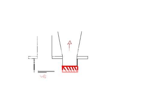
here is a sideview of what i am trying to explain/accomplish with the transition.
we have to run a 19mm restrictor before the turbo, so if we can make 80-90hp we will be doing pretty well. we are trying to make midrange gains before we chokeflow the restrictor. hopefully the broader powerband will allow us to shift less during competition.
here is a sideview of what i am trying to explain/accomplish with the transition.
12-04-2006, 08:26 AM
#7
Honda-Tech Member
Thread Starter
Join Date: Jan 2003
Location: the backwoods, usa
Posts: 2,841
Likes: 0
Received 0 Likes
on
0 Posts
<TABLE WIDTH="90%" CELLSPACING=0 CELLPADDING=0 ALIGN=CENTER><TR><TD>Quote, originally posted by Schister66 »</TD></TR><TR><TD CLASS="quote">i would not be putting the small end of that transition inside of the flange.....weld that to the flat part of the flange rather than putting it inside....</TD></TR></TABLE>
what's your reasoning behind that??
it wont go down to the wheel. just to the casting. i screwed up my drawing a little bit. if you look at the very first picture you can see where the casting is and the wheel sits down in a ways..
what's your reasoning behind that??
it wont go down to the wheel. just to the casting. i screwed up my drawing a little bit. if you look at the very first picture you can see where the casting is and the wheel sits down in a ways..
Trending Topics
12-04-2006, 09:10 AM
#8
Honda-Tech Member
Join Date: Jan 2005
Location: b00sting my D16s, SoWis, USA
Posts: 7,015
Likes: 0
Received 7 Likes
on
5 Posts
I saw a good post recently (maybe it was blundar), but they had good 'technical' reasoning. The manifold pressure is almost always much higher than post-turbo pressure. You most likely know gasses try to equalize pressure, so it uses that concept. The less pressure you have after the turbine, the more energy the gasses will exert on the turbine wheel as they pass, as they want to flow faster. If you want to look at it one way, the energy is used to spin the wheel rather than push post-turbo gasses out of the way.
Basicly, bigger is better. Cars that change from open downpipe to full exhaust loose 20+ whp, and that can alther the A/F by as much as a full point.
Now for the flange, I'd suggest going with the largest pipe possible. I'm assuming you have more than just a hacksaw and a hammer, so I'd say take a round tube and shape it to those two ports (think two overlapping circles). Due to the restrictor, you'll have less flow than normal near redline, so problems with WG gas pressure shouldn't be an issue. You really don't want a seperate 'dump tube' for the WG anyways, since the ports aren't segregated in the housing. The axial airflow through the turbine will try shooting air in a reverse cone, so technically the flange division would be a blockage.
As for dealing with the restrictor, try making a velocity stack for the turbo, and try enlarging the intake pipe before/after the restrictor. I'd rather loose power from compressing the air at the restrictor (venturi) than from reducing flow over the entire intake.
12-04-2006, 09:15 AM
#9
Honda-Tech Member
Thread Starter
Join Date: Jan 2003
Location: the backwoods, usa
Posts: 2,841
Likes: 0
Received 0 Likes
on
0 Posts
thanks for the replies guys. keep them coming 
has anyone ever tried this on a small internally gated turbo??
on all the DPs i've made for small turbos (T25s, IHIs, etc.) i have always done it simular to the way everyone is saying. i just figured that by doing this maybe i can keep velocity up coming off the wheel.
has anyone ever tried this on a small internally gated turbo??
on all the DPs i've made for small turbos (T25s, IHIs, etc.) i have always done it simular to the way everyone is saying. i just figured that by doing this maybe i can keep velocity up coming off the wheel.
12-04-2006, 09:37 AM
#12
Honda-Tech Member
imo, leave the wg & exh separate.
run the bigest o.d. tube you can fit on that flange with the bolts,
install a divider in the turbine outlet(between the wg flapper/turbine discharge) so the 2 dont "mix" with eachother.
a large diameter, short wg dump tube "should" control the boost better. than say a longer tube. less friction.
aluminum downpipe would be beneficial as well. it will help cool the exh gas. which will help get it out of the system faster.. then say a stainless "counterpart" which will hold the heat in (expand'd gas's) causing more friction inside the dp.
Modified by dturbocivic at 1:47 PM 12/4/2006
12-04-2006, 10:05 AM
#13
Man U FTW
^^I agree....i have watched my close friend matt do a lot of welding (manifolds and such) and i haven't ever seen him put a pipe inside the hole diameter of a flange. Everyone i have seen building a manifold, dp or whatever, has always welded the pipe flat to the flange because the diameter of the pipe was larger than that of the flange.
12-05-2006, 03:39 PM
#15
Honda-Tech Member
Join Date: Feb 2004
Location: not riding any bandwagons in, massachusetts, usa
Posts: 1,592
Likes: 0
Received 0 Likes
on
0 Posts
on second thought, one more adjustment.
get another transition like the one youve got and put it backwards so its a converging taper, like a funnel collecting at the wastegate and reducing down to the exhaust diameter.
you dont see 90 degree exhaust seats in an engine, you see multi-angle or radius because it helps collect and file gas molecules into a streamline to travel through a conduit. make that shape after your wastegate flapper.
try to put as much radius into the face of it as possible with welding/grinding.
thats a damn nice setup btw. looks like a burns collector, even better is a smallish main diameter that feeds the turbine, and its got a good distance after the collector merge for flow to straighten out, you guys didyour homework. dont be afraid to fab a straight shot external wastegate port right in front of that merge (and as far from turbine as possible) if the rules allow. you can use a turnbuckle to bind your internal wastegate and run the external, or cap the external and run the internal to test side by side performance of wastegating and (intake /to/ exhaust /to/ downpipe) pressure ratios. whatever that thing is, it has the potential to be dangerously fast. be careful.
12-08-2006, 09:52 AM
#16
Honda-Tech Member
Join Date: Jan 2005
Location: b00sting my D16s, SoWis, USA
Posts: 7,015
Likes: 0
Received 7 Likes
on
5 Posts
<TABLE WIDTH="90%" CELLSPACING=0 CELLPADDING=0 ALIGN=CENTER><TR><TD>Quote, originally posted by mike_belben@yahoo.com »</TD></TR><TR><TD CLASS="quote">you dont see 90 degree exhaust seats in an engine, you see multi-angle or radius because it helps collect and file gas molecules into a streamline to travel through a conduit. make that shape after your wastegate flapper.</TD></TR></TABLE>
You also don't see hogged-out ports on high-flowing heads, or plentums starting 1/4" from the head. Intake is a whole different ballgame than exhaust gasses, especially when its post-turbine gasses. In this case, where the turbine wheel & WG ports will mix regardless due to the 'open' cast section, you want the most volume after the turbo. Look at how a flash suppressor works on a gun - considerable amount of the gasses shoot out to the side. Since those ports are connected in the casting, having 2 smaller seperated ports rather than 1 much larger port wouldn't make sense. I *highly* doubt that he'll have WG-induced backpressure issues, due to the 19mm restrictor before the turbo. It just won't flow up top to even be using the wastegate in the sense Honda FI guys are used to. If anyone here can't relate sizes, a 56mm D16 throttle body has a cross-section of ~2100mm^2 (after removing area of the butterfly), and lohatch's mandated 19mm restrictor has a cross-section of 336mm^2. Thats just 16% of what a crappy D16 t-body can pass through it. Hell, a single D16 valve is 30mm in size...
When it comes to post-turbo gasses, low backpressure > gas velocity. Low backpressure designs increase turbo exhaust velocity.
<U>Cliffs:</U>
lohatch has a huge restriction pre-turbo. 15% of what a 60mm t-body will flow.
Said restriction will lead to heavy high-rpm suffocation.
Said suffocation will not allow for 'typical' exhaust energy after spool up from a FI motor.
Turbos make huge power with low-energy exhaust gasses when you have zero pressure after the exducer.
<U>Said motor should have as much freaking volume after the turbo.</U>
You also don't see hogged-out ports on high-flowing heads, or plentums starting 1/4" from the head. Intake is a whole different ballgame than exhaust gasses, especially when its post-turbine gasses. In this case, where the turbine wheel & WG ports will mix regardless due to the 'open' cast section, you want the most volume after the turbo. Look at how a flash suppressor works on a gun - considerable amount of the gasses shoot out to the side. Since those ports are connected in the casting, having 2 smaller seperated ports rather than 1 much larger port wouldn't make sense. I *highly* doubt that he'll have WG-induced backpressure issues, due to the 19mm restrictor before the turbo. It just won't flow up top to even be using the wastegate in the sense Honda FI guys are used to. If anyone here can't relate sizes, a 56mm D16 throttle body has a cross-section of ~2100mm^2 (after removing area of the butterfly), and lohatch's mandated 19mm restrictor has a cross-section of 336mm^2. Thats just 16% of what a crappy D16 t-body can pass through it.
Hell, a single D16 valve is 30mm in size...When it comes to post-turbo gasses, low backpressure > gas velocity. Low backpressure designs increase turbo exhaust velocity.
<U>Cliffs:</U>
lohatch has a huge restriction pre-turbo. 15% of what a 60mm t-body will flow.
Said restriction will lead to heavy high-rpm suffocation.
Said suffocation will not allow for 'typical' exhaust energy after spool up from a FI motor.
Turbos make huge power with low-energy exhaust gasses when you have zero pressure after the exducer.
<U>Said motor should have as much freaking volume after the turbo.</U>
12-08-2006, 09:58 AM
#17
Member
Join Date: May 2004
Location: Nashville, TN, U.S.A
Posts: 2,992
Likes: 0
Received 0 Likes
on
0 Posts
<TABLE WIDTH="90%" CELLSPACING=0 CELLPADDING=0 ALIGN=CENTER><TR><TD>Quote, originally posted by lohatch »</TD></TR><TR><TD CLASS="quote">minnesota state mankato</TD></TR></TABLE>
I'd help you out, but our UMR FSAE team has a turbo in the works as well.
GL though. There are ways around the restriction that can make things flow better.
I'd help you out, but our UMR FSAE team has a turbo in the works as well.
GL though. There are ways around the restriction that can make things flow better.
12-08-2006, 02:44 PM
#18
Honda-Tech Member
Join Date: Feb 2004
Location: not riding any bandwagons in, massachusetts, usa
Posts: 1,592
Likes: 0
Received 0 Likes
on
0 Posts
HiProfile- your response has a hint of "well its got a restrictor screwing everything else up, dont bother rounding that corner or paying much attention to that other detail, its a waste of time."
how would you have responded if there was not an inlet restrictor?
i wont argue with your information, most anyone has more turbo experience than me. volume vs velocity is one big aspect with lots of room for E-battles that could be squashed with just a few pressure graphs of dedicated tests. and im not sure which side to be on.
im an advocate of maximum pressure differential across a turbine wheel via small volume manifold, large volume exhaust (and of wastegates capable of bypassing nearly the entire engine volume if required so that exhaust port pressure can be the absolute minimum required to sustain a preset intake pressure level).. however i dont just throw flow quality out the window. enough turbulence could probably create an internal eddy that caused enough fluid friction for pressure to rise, even though the volume was considerably large. who knows which sharp edge or square corner will create that turbulent wake? maybe you do, but since i dont, i like to pay attention to those possibly offending edges before they are giving me unexplained issues down the road. in a case like this, i think it is worth the time, restrictor or not.
12-09-2006, 11:50 AM
#20
Honda-Tech Member
Join Date: Jan 2005
Location: b00sting my D16s, SoWis, USA
Posts: 7,015
Likes: 0
Received 7 Likes
on
5 Posts
<TABLE WIDTH="90%" CELLSPACING=0 CELLPADDING=0 ALIGN=CENTER><TR><TD>Quote, originally posted by mike_belben@yahoo.com »</TD></TR><TR><TD CLASS="quote">how would you have responded if there was not an inlet restrictor?</TD></TR></TABLE>
Run an even larger tube, but pinch it down to that size...
<TABLE WIDTH="90%" CELLSPACING=0 CELLPADDING=0 ALIGN=CENTER><TR><TD>Quote, originally posted by mike_belben@yahoo.com »</TD></TR><TR><TD CLASS="quote">im an advocate of maximum pressure differential across a turbine wheel ...
... enough turbulence could probably create an internal eddy that caused enough fluid friction for pressure to rise, even though the volume was considerably large. who knows which sharp edge or square corner will create that turbulent wake?</TD></TR></TABLE>
#1 Advocating max pressure diff across the turbine means you understand that gases before the turbine are under much higher pressures than after.
#2 You understand air movement can cause friction and turbulance, which can lead to backpressure in this situation.
#3 His housing connects both ports in the housing, and there's not one thing he can do to change that, besides risking welding a divider into the housing. He'll get turbulance regardless of 1 big or 2 small ports.
If you look at his picture, with 2 tubes and the wastegate closed, gas from the large port will seek the smaller port once any bit of pressure exists in the larger pipe. With the wastegate open, gases from both will mingle before the flange, and try equalizing pressure between the segregated pipes.
Lets say its a single 4" pipe vs. a 3" and 1". Even if they are totally seperate, They amount to a cross-section of < 8 in^2 together. A 4" has a > 12.5 in^2 cross-section. I can't think how eddies and turbulance will reduce the flow of a 12.56 in^2 port to that of a 7.85 in^2 port - that would require a 40% reduction! Not only that, but we're assuming the smaller one has no turbulance/eddies - in this case it will.
If the housing looked like a DSM housing (wg/wheel ports are seperated all the way to the flange), I'd erase my posts and suggest two separate pipes w/gradual transitions. It does not, so I fall back to 'no DP is the best DP for a turbo', IE the most reasonable volume you can make.
BTW to OP - see if you can try 'accidentally warping' the surface of the intake flange. Its a restrictor, not a mass air flow sensor...so bypass it!
12-09-2006, 12:32 PM
#21
Honda-Tech Member
Join Date: Feb 2004
Location: not riding any bandwagons in, massachusetts, usa
Posts: 1,592
Likes: 0
Received 0 Likes
on
0 Posts
after taking some time to think, i will accept all of the things you said as true, though i still think semi dividing them would be a large improvement over not doing so at all, he is headed in the right direction.
i suppose the best case scenario then will be to fabricate a sheetmetal box the shape of the housing outline, create a tight fitting internal divider, then taper it all down to the exhaust diameter. it would look like a vaccuum cleaner attatchment with a plate splitting the two sides for as deep a length as possible. maybe a hole or two in the divider could help immediately equalize pressure so that the merge area all flows smoothly. it might not be that difficult to squeze a large diameter tube and do a little hammering to get the mouth to flare just right rather than doing an actual box.
-edit-
that does not mean i am saying which one i think would or wouldnt have more pressure or would make better power. i am agreeing that dividing the two but having them still connected via small gaps would create a difference of pressure that would seek equilibrium, inducing turbulence of atleast slight amounts. the box would create a common plenum, therefore a common pressure. it may or may not have the least pressure. something ill try to test out in the next year.

Thread
Thread Starter
Forum
Replies
Last Post
O16581724 5 2 5
Forced Induction
13
12-17-2005 06:41 AM