

3 bar install help

Honda-Tech Member
Joined: Dec 2003
Posts: 630
Likes: 0
From: Socal, 91 oct sucks, USA
Info from G2IC Turbo guide by Haberdasher.
link: http://www.beesandgoats.com/bo...ement
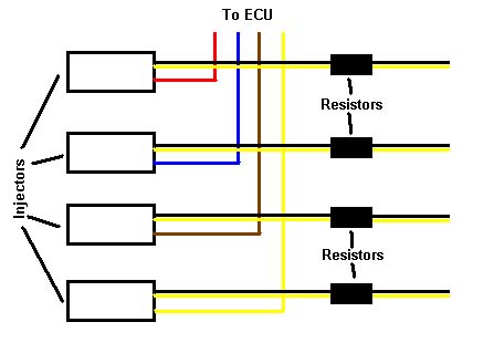
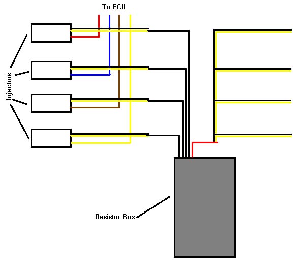
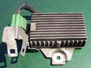
If you chose to wire in resistors inline on each injector wire then you will need 10watt 10ohm resistors (they look like the picture below) which can be found at Radio Shack. Solder one resistor into each black and yellow wire for each injector (see wiring diagram below). If you chose to use the resistor box (see picture below) then you will need to do a bit more cutting and soldering. The resistor box has 4 black wires and one red wire. After cutting the black and yellow wires solder each of the black wires from the resistor box to each of the black and yellow wire that leads to the injectors, it does not matter which black wire in the resistor box goes to which injector. Be sure the black and yellow wires you find are actually the injector wires by checking for continuity on the injector connector. Now we need to connect the red wire from the resistor box to all 4 of the other black and yellow wires. It is best to use a butt connector to do this, if you try to solder all these wires together you will end up with a large ball of solder. See the wiring diagram below for using the resistor box.
link: http://www.beesandgoats.com/bo...ement
If you chose to wire in resistors inline on each injector wire then you will need 10watt 10ohm resistors (they look like the picture below) which can be found at Radio Shack. Solder one resistor into each black and yellow wire for each injector (see wiring diagram below). If you chose to use the resistor box (see picture below) then you will need to do a bit more cutting and soldering. The resistor box has 4 black wires and one red wire. After cutting the black and yellow wires solder each of the black wires from the resistor box to each of the black and yellow wire that leads to the injectors, it does not matter which black wire in the resistor box goes to which injector. Be sure the black and yellow wires you find are actually the injector wires by checking for continuity on the injector connector. Now we need to connect the red wire from the resistor box to all 4 of the other black and yellow wires. It is best to use a butt connector to do this, if you try to solder all these wires together you will end up with a large ball of solder. See the wiring diagram below for using the resistor box.

Honda-Tech Member
Joined: Dec 2003
Posts: 630
Likes: 0
From: Socal, 91 oct sucks, USA
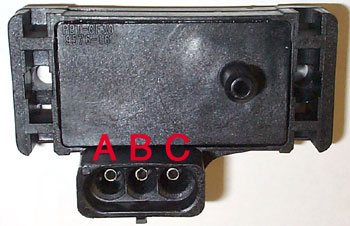
Using a multimeter check
A - Ground using the resistance part of a multimeter it should read 00.00
C - Click to the proper DC range on a multimeter to check for 5 volts
B - By process of elimination this should be your map signal wire
A - Ground using the resistance part of a multimeter it should read 00.00
C - Click to the proper DC range on a multimeter to check for 5 volts
B - By process of elimination this should be your map signal wire
Trending Topics

Junior Member
Joined: Sep 2002
Posts: 646
Likes: 0
From: minot, nd, 58701
check this out. leave your stock map hooked up to the connector. cut the insulation of each wire to expose the bare wire (since your gonna be splicing it anyways). now check for voltage, turn your ignition on. probe to the wires,
A- ground
B-map sig (2.8)
C-5v
pick any two wires and probe to it, this should give you an idea of which wire is which. for example, neg. lead to C and pos. lead to B=no reading which means that those two wires isn't your ground wire. now for example, neg. lead to C and pos. lead to A= you get a reading of -5v, which means that your polarity is switch. switch your leads around, and now you have found two wires that work and one of them may be your ground.
leaving one meter lead hooked up to A or C probe to the third wire if you get a reading of 2.8v then you've found your map sig. if not do the same to the other lead.
remember to leave the connector hooked up and turn the ignition on.
hope that helps, hope i wrote well enough, hope you get it.
Honda-Tech Member
Joined: Dec 2003
Posts: 630
Likes: 0
From: Socal, 91 oct sucks, USA
To check which wire is ground:
First click to the resistance part of your multimeter. Then have the black test lead of your multimeter touch or clip onto the ground strap of your motor. If it doesn't reach have it touch any bare metal (no painted surface). With the red test lead probe each wire on the map sensor clip. Ground will read 00.00 or close to it.
Then for voltage:
Click your multimeter to the DC range that will read 5v. Then have the black test lead of your multimeter touch or clip onto the ground strap of your motor. If it doesn't reach have it touch any bare metal (no painted surface). With the red test lead probe the other two wires to see which reads 5v and do the same for the 2.8volts


Thread
Thread Starter
Forum
Replies
Last Post
importimage
Hybrid / Engine Swaps
15
Oct 31, 2003 09:07 PM
Happyman
Forced Induction
26
Aug 26, 2003 09:08 PM