

rusEfi - DIY ems build thread


Thread Starter
Honda-Tech Member
Joined: Jul 2014
Posts: 42
Likes: 0
From: Jersey City, USA
For the last two years I am playing with my own from scratch ECU. A week ago I've got a new test mule - surprise-surprise it's a honda, so hopefully it would be fine to start a thread here 

Thread Starter
Honda-Tech Member
Joined: Jul 2014
Posts: 42
Likes: 0
From: Jersey City, USA
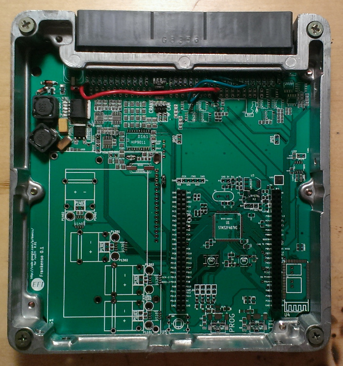
Just got a new board - so far the power supply works and I am now trying to figure out VR trigger input. Please tell me it is VR in this 1995 Accord distributor?
Couple of links Re: this project: http://hackaday.com/2014/03/29/frank...-control-unit/ http://www.autoweek.com/article/2014...WS02/140429923
Hopefully it's appropriate to post this here. This is not a commercial product - this is an open source work-in-progress projects, so hopefully I am not breaking the forum rules.
Thread Starter
Honda-Tech Member
Joined: Jul 2014
Posts: 42
Likes: 0
From: Jersey City, USA
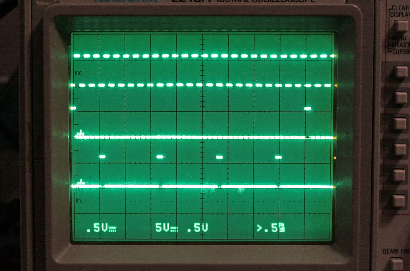
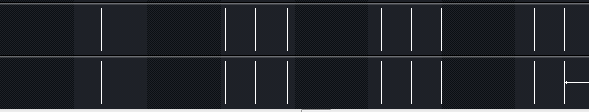
I am using max9926 chip for VR trigger signal input, here's what I get for TDC and CKP signals:
Does anyone has a description of the signal shape, the angles at which these rises and falls are happening?
Does anyone has a description of the signal shape, the angles at which these rises and falls are happening?
DO IT ON ALL FOURS
Joined: Sep 2007
Posts: 7,632
Likes: 15
From: IN Your Mind
You are in the wrong place and time for this kind of information. Nobody really cares anymore since most EMSs have been figured out YEARS ago and most systems are built on proven foundations - the factory Honda OBD-1 ECU. The place to go would have been www.pgmfi.org if there are any knowledgeable members even left over there. A lot of them even went on to make their own EMS.
You are in the wrong place and time for this kind of information. Nobody really cares anymore since most EMSs have been figured out YEARS ago and most systems are built on proven foundations - the factory Honda OBD-1 ECU. The place to go would have been www.pgmfi.org if there are any knowledgeable members even left over there. A lot of them even went on to make their own EMS.
Trending Topics
Thread Starter
Honda-Tech Member
Joined: Jul 2014
Posts: 42
Likes: 0
From: Jersey City, USA
Yes its been done, and done well.
AEM EMS
Motec
MegaSquirt is more DIY but has all the functionality you want.
Are you not aware of these systems? They will support any and all triggers and inputs/outputs you want.
AEM EMS
Motec
MegaSquirt is more DIY but has all the functionality you want.
Are you not aware of these systems? They will support any and all triggers and inputs/outputs you want.
Thread Starter
Honda-Tech Member
Joined: Jul 2014
Posts: 42
Likes: 0
From: Jersey City, USA
Oh, I am absolutely aware that there are plenty of standalone EMS systems around.
Please remind me which of these is open source? I am sure you would not make the mistake on calling MS open source.
Please remind me which of these is open source? I am sure you would not make the mistake on calling MS open source.
Honda-Tech Member
Joined: Mar 2007
Posts: 11,399
Likes: 70
From: East Coast 506, Canada
To be honest I don't think there are many on here that spend much time on open source engine management and scratch built ECU's.
If you are looking for sensor input data MegaSquirt sites would be a good place to go. Even though it's not "Open Source" Quite a few of the people who use it, share a lot of the background electronics information. These users cover a very wide base of automotive OEM's specs.
If you are looking for sensor input data MegaSquirt sites would be a good place to go. Even though it's not "Open Source" Quite a few of the people who use it, share a lot of the background electronics information. These users cover a very wide base of automotive OEM's specs.


I love seeing DIY stuff, who cares if its been done before.
Nothing wrong with starting out with a DIY project, a lot of the go-to companies in this industry were started by noodling around at their own workbench. It's a great learning experience and who knows what you'll come up with next. I'm in to see the final project.
Build something that runs on a more capable processor than the dinosaur obd1 ecus (and maybe even has at least limited obd2 capability) and you'll have something, if you ask me.
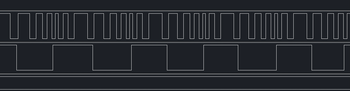
I've found from building my sim that the stock ECU isn't super picky about the shape, it's looking for the zero crossing in the right phase relative to the other sensors. I was able to keep it happy by pushing a set of 5V square waves (properly timed of course) through an rs-232 ship to amplify them and impart the zero crossing.
Since your ECU will probably want a TTL signal, you can probably run through a comparator (as the stock ecu does) or maybe even run through the logic converter as I did, but in the other direction.
Here's what you are looking for:
Pattern:

Shape:
Good luck.
Nothing wrong with starting out with a DIY project, a lot of the go-to companies in this industry were started by noodling around at their own workbench. It's a great learning experience and who knows what you'll come up with next. I'm in to see the final project.
Build something that runs on a more capable processor than the dinosaur obd1 ecus (and maybe even has at least limited obd2 capability) and you'll have something, if you ask me.
I've found from building my sim that the stock ECU isn't super picky about the shape, it's looking for the zero crossing in the right phase relative to the other sensors. I was able to keep it happy by pushing a set of 5V square waves (properly timed of course) through an rs-232 ship to amplify them and impart the zero crossing.
Since your ECU will probably want a TTL signal, you can probably run through a comparator (as the stock ecu does) or maybe even run through the logic converter as I did, but in the other direction.
Here's what you are looking for:
Pattern:
Shape:
Good luck.
Thread Starter
Honda-Tech Member
Joined: Jul 2014
Posts: 42
Likes: 0
From: Jersey City, USA
You'll see it here This thingy has already started four engines in three countries, it just needs a lot of extra polishing and more driving miles put on it.
The chip we are using is 168Mhz - that's probably 5-10 times faster then what was used back in the 90s. Hopefully the extra performance would allow us to add extra capabilities. This board has a CAN chip on in so OBDII-via-CAN is totally possible.
We are using that max9926 - it's a purpose-build chip for VR signal conditioning. I am not an EE so I am not sure what's the point, all I know is that it has better reviews then LM1815. That black&white picture is the TTL signal produces by that chip - it only has two channels so we would probably need to add a third one in the next edition.
Thank you, and really appreciate the pictures - that's huge help.
This thingy has already started four engines in three countries, it just needs a lot of extra polishing and more driving miles put on it.
Thank you, and really appreciate the pictures - that's huge help.
Thread Starter
Honda-Tech Member
Joined: Jul 2014
Posts: 42
Likes: 0
From: Jersey City, USA
Another question if that's OK: CLT and IAT sensor data? I need resistance at three temperature points to build the curve. Asking @ http://www.msextra.com/forums/viewto...p?f=71&t=55191 as was suggested did not really help 
The sensor part numbers are 37870-PJ7-003 and 37880-P0A-A02 if that would help.
The sensor part numbers are 37870-PJ7-003 and 37880-P0A-A02 if that would help.
You can estimate it from a factory service manual if yo have access to one. They're fairly linear actually, but the best thing to do would be to set it up with a voltage divider circuit and do grab some data points (5-7 should do). Do a polynomial curve fit in Excel or whatever and create a lookup table for an 8-bit ADC to save processor. No sense calculating it every time by.
Here's the graph from the FSM, this should get you in the ballpark:

IAT is the same iirc.
Here's the graph from the FSM, this should get you in the ballpark:

IAT is the same iirc.
Last edited by spAdam; Jul 24, 2014 at 05:22 PM.
Thread Starter
Honda-Tech Member
Joined: Jul 2014
Posts: 42
Likes: 0
From: Jersey City, USA
I think this picture is misleading a bit - looks like resistance scale is not linear, thus the nearly straight line is actually a curve once you get to linear scale on the axis.
I'm using the 'fancy' http://rusefi.com/articles/measuring...art-Hart.shtml and yes, it has already hit me a bit - the 'log' operation is reeeeallly heavy. Since these temperatures do not change that fast, I will probably limit this math to couple of times a second. Couple of times a second I can afford it
As for the table lookup, that's fast but that cost you memory
As for the table lookup, that's fast but that cost you memory
Thread Starter
Honda-Tech Member
Joined: Jul 2014
Posts: 42
Likes: 0
From: Jersey City, USA
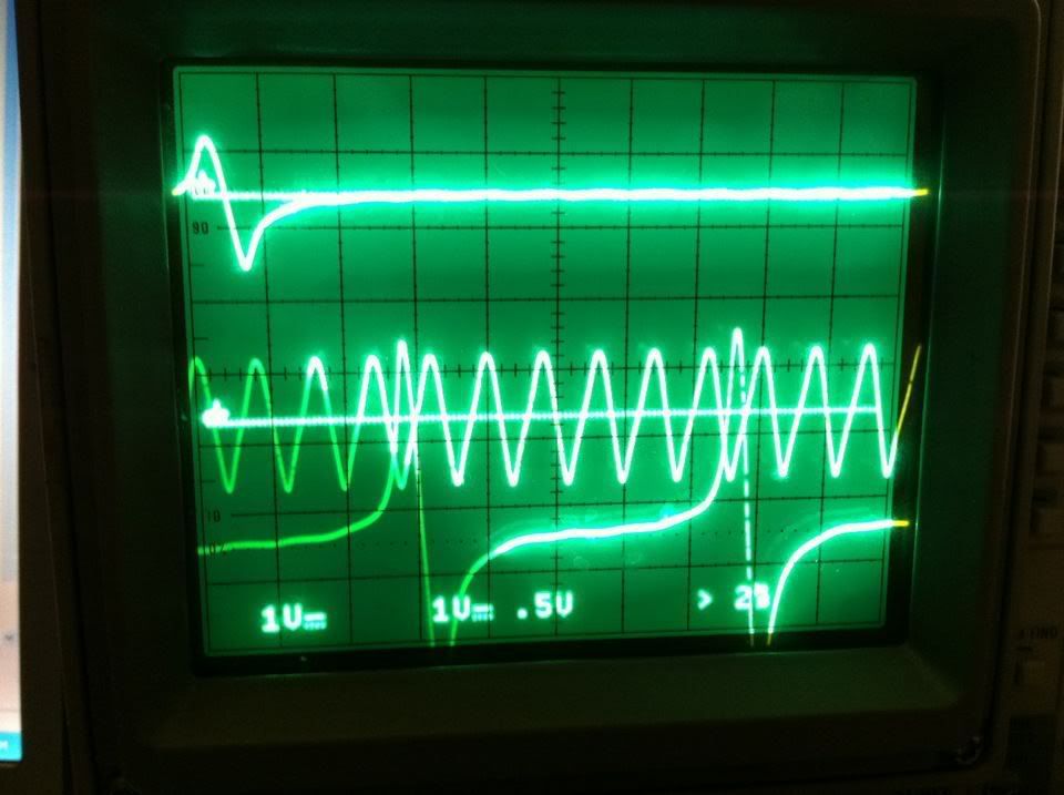
So with my board I have that weird noise issue: with ignition ON position and engine stopped, I have the following ~40Hz signal/noise on the CKP/TDC VR output. As a workaround, I've found that I need to disconnect TCM plug A and the noise would be gone.
Makes me question if any of the TCM plug A wires carries some digital signal? For now I will just have this plug off, but at some point I would need to turn it on.
Makes me question if any of the TCM plug A wires carries some digital signal? For now I will just have this plug off, but at some point I would need to turn it on.
Cool progress.
You're right, it's not very linear. I thought I remembered it being more so but then when I pulled the snip I saw otherwise.
There's no real reason to poll the temp sensors at more than .5-1Hz in my opinion. As you stated, they just don't change that fast.
As far as costing memory, it's always cheaper than processor. Lookup tables also work nice and fast if you're relying on your processor to tick through operations quickly. The obd1 Honda ecus use plenty of lookup tables (think ECT & IAT comps) to save processor resources. You also don't need as much resolution as a constant calculation will provide. If you use a 16 bit ADC to convert the temp sensor you'll have 256 values which is still significantly better than you need to get things running correctly, and you can approximate both sensors from the same table.
I think this picture is misleading a bit - looks like resistance scale is not linear, thus the nearly straight line is actually a curve once you get to linear scale on the axis.
I'm using the 'fancy' http://rusefi.com/articles/measuring...art-Hart.shtml and yes, it has already hit me a bit - the 'log' operation is reeeeallly heavy. Since these temperatures do not change that fast, I will probably limit this math to couple of times a second. Couple of times a second I can afford it
As for the table lookup, that's fast but that cost you memory
There's no real reason to poll the temp sensors at more than .5-1Hz in my opinion. As you stated, they just don't change that fast.
As far as costing memory, it's always cheaper than processor. Lookup tables also work nice and fast if you're relying on your processor to tick through operations quickly. The obd1 Honda ecus use plenty of lookup tables (think ECT & IAT comps) to save processor resources. You also don't need as much resolution as a constant calculation will provide. If you use a 16 bit ADC to convert the temp sensor you'll have 256 values which is still significantly better than you need to get things running correctly, and you can approximate both sensors from the same table.
Thread Starter
Honda-Tech Member
Joined: Jul 2014
Posts: 42
Likes: 0
From: Jersey City, USA
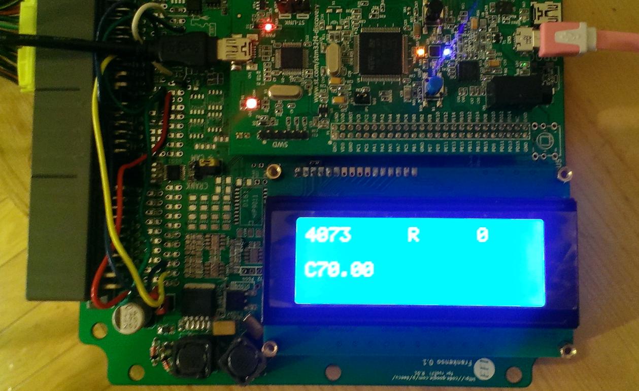
turns out there are some routing bugs on the board - SD card is not routed properly, that would be something to fix in the next revision. the board looks pretty sweet with an LCD screen:
Now a question: what are the characteristics of my stock MAP sensor? I believe it is linear, so I just need two points to build the line.
Now a question: what are the characteristics of my stock MAP sensor? I believe it is linear, so I just need two points to build the line.
Thread Starter
Honda-Tech Member
Joined: Jul 2014
Posts: 42
Likes: 0
From: Jersey City, USA
Honda-Tech Member
Joined: Mar 2007
Posts: 11,399
Likes: 70
From: East Coast 506, Canada
Ambient pressure would depend on your geographical location vs sea level.
29.92 in. Hg is sea level.
Pressure decreases 0.368 inHg every 100m above sea level. (15�C and 0% relative humidity)
I'm not 100% on the variance of the voltage/pressure. All of my old Crome datalogs are corrupted when I open them in the newer version. All I am going by here is the data that Honda has provided for diagnostics and troubleshooting the MAP sensor. Hopefully someone who has logged actual data will chime in.
Thread Starter
Honda-Tech Member
Joined: Jul 2014
Posts: 42
Likes: 0
From: Jersey City, USA
Does anyone know anything about the wires between ECU and TCM?
I am using the diagram: https://i.imgur.com/eMzLNjz.png https://i.imgur.com/CNoS46a.png
1) it shows a BRN/WHT wire, it's called 'shift acknowledgement' on the TCM side and FAS on the ECU side. what does 'FAS' stand for? Digital/analog? What's the protocol?
2) Up/Down shift signals are called AFSA & AFSB on the ECU side, what do these acronyms stand for? Digital/analog? What's the protocol?
3) Baro out? There is no dedicated Baro sensor, so I guess that's something made of MAP?