


push button kill switch


They let me pick
Joined: Jun 2005
Posts: 3,690
Likes: 1

Thread Starter
Junior Member
Joined: Oct 2009
Posts: 26
Likes: 0
well i was thinking of something, cut the ignition wire that leads to the started, take the fuse box off, rewire it, hide the switch so that i can just kick it, or push it in as i crank the engine, and bam done i think. unless it has to keep feeding power, i don't know if you guys know that i mean, would like some opinions
Old Fart
Joined: May 2004
Posts: 26,173
Likes: 18
From: kelowna, bc, canada
You can use the switch to control a latching relay, the latching relay can be installed on any wire you want, it will latch, [close] when the ign. is turned on and you press the momentary switch, [button], it will stay latched until you turn the ign. switch off, [passive "arming"], a latching relay can be made with two standard automotive SPDT relays. 94
Trending Topics
Old Fart
Joined: May 2004
Posts: 26,173
Likes: 18
From: kelowna, bc, canada
You need two SPDT relays, call them relay 1 and relay 2.
Relay 1 is the "kill" relay so #30 ands #87 will be from the cut ends of whatever wire your "killing", [starter, ign. power or grounds to ECU/ECM and so on], it makes no diff. if the lead you cut is pos.(+) or neg.(-) low or high current.
#85 of relay 1 needs a "true ign", [hot in run and start] should be a fused line, [5A max].
#86 of relay 1 connects to #87 of relay 2.
Relay 2 is the latching relay so #30 goes to chassis ground and #87 is connected, [daisy chained] to #86 and #86 is also connected to one side of the momentary switch, other side of switch goes to chassis ground.
#85 of relay 2 also needs a "true ign.", can be the same fuse lead as goes to #85 of relay 1
Yes, #86 of relay 1 and #87 and #86 of relay 2 are all connected together, [daisy chained] and go to the momentary switch, when the ign. is on and you press the switch a ground will be supplied to #85 of both relays, energizing them, when relay 2 is energized it will connect #30, [ground] and #87, #87 will in turn supply the ground needed to "latch" the relays.
When the ign. is turned off the relays will de-energize and the connection of #30 and #87 of relay one will open. 94
Last edited by fcm; Nov 10, 2009 at 04:28 PM. Reason: typo
Honda-Tech Member
Joined: Jan 2004
Posts: 4,407
Likes: 5
From: Locash
There is no "ignition lead to the starter". Ignition is one circuit. Starter is a separate circuit.
I would interrupt the starter wire with a relay, then have the momentary pushbutton (normally open) control the relay. Hold the button down while cranking.
But that wouldn't be very effective. Main relay kill is the way to go.
I would interrupt the starter wire with a relay, then have the momentary pushbutton (normally open) control the relay. Hold the button down while cranking.
But that wouldn't be very effective. Main relay kill is the way to go.

Trial User
Joined: Jul 2010
Posts: 1
Likes: 0
You need two SPDT relays, call them relay 1 and relay 2.
Relay 1 is the "kill" relay so #30 ands #87 will be from the cut ends of whatever wire your "killing", [starter, ign. power or grounds to ECU/ECM and so on], it makes no diff. if the lead you cut is pos.(+) or neg.(-) low or high current.
#85 of relay 1 needs a "true ign", [hot in run and start] should be a fused line, [5A max].
#86 of relay 1 connects to #87 of relay 2.
Relay 2 is the latching relay so #30 goes to chassis ground and #87 is connected, [daisy chained] to #86 and #86 is also connected to one side of the momentary switch, other side of switch goes to chassis ground.
#85 of relay 2 also needs a "true ign.", can be the same fuse lead as goes to #85 of relay 1
Yes, #86 of relay 1 and #87 and #86 of relay 2 are all connected together, [daisy chained] and go to the momentary switch, when the ign. is on and you press the switch a ground will be supplied to #85 of both relays, energizing them, when relay 2 is energized it will connect #30, [ground] and #87, #87 will in turn supply the ground needed to "latch" the relays.
When the ign. is turned off the relays will de-energize and the connection of #30 and #87 of relay one will open. 94
Relay 1 is the "kill" relay so #30 ands #87 will be from the cut ends of whatever wire your "killing", [starter, ign. power or grounds to ECU/ECM and so on], it makes no diff. if the lead you cut is pos.(+) or neg.(-) low or high current.
#85 of relay 1 needs a "true ign", [hot in run and start] should be a fused line, [5A max].
#86 of relay 1 connects to #87 of relay 2.
Relay 2 is the latching relay so #30 goes to chassis ground and #87 is connected, [daisy chained] to #86 and #86 is also connected to one side of the momentary switch, other side of switch goes to chassis ground.
#85 of relay 2 also needs a "true ign.", can be the same fuse lead as goes to #85 of relay 1
Yes, #86 of relay 1 and #87 and #86 of relay 2 are all connected together, [daisy chained] and go to the momentary switch, when the ign. is on and you press the switch a ground will be supplied to #85 of both relays, energizing them, when relay 2 is energized it will connect #30, [ground] and #87, #87 will in turn supply the ground needed to "latch" the relays.
When the ign. is turned off the relays will de-energize and the connection of #30 and #87 of relay one will open. 94

Hopefully I got it all right
 It looks a little different than the schematic on the12volt.com
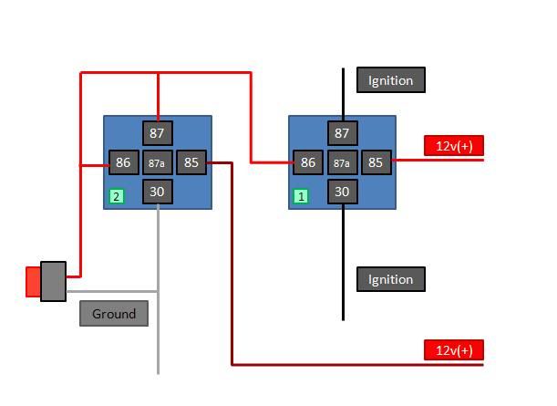

Old Fart
Joined: May 2004
Posts: 26,173
Likes: 18
From: kelowna, bc, canada
Hatch, your single relay works fine on the starter lead, it will not work on any other lead. 94

Honda-Tech Member
Joined: Sep 2008
Posts: 107
Likes: 0
From: seattle, wa
If you have a steering wheel with two horn buttons, or an aftermarket, wire it to the horn is the best place. Whos gonna hit the horn button in the middle of the night when trying to steal it, Theifs are not going to think of testing out the horn button in the middle of the night when they are stealing cars. To risky to try. Just my advice
Honda-Tech Member

Joined: Jul 2009
Posts: 1,030
Likes: 0
From: ☆★ ℂolorado ★☆
If you have a steering wheel with two horn buttons, or an aftermarket, wire it to the horn is the best place. Whos gonna hit the horn button in the middle of the night when trying to steal it, Theifs are not going to think of testing out the horn button in the middle of the night when they are stealing cars. To risky to try. Just my advice
Now I wish I didnt have my nitrous button hooked up to my horn lol
I was thinking about using the AC button as well (since I dont have AC), but not sure how the wiring on that is.


Thread
Thread Starter
Forum
Replies
Last Post
6KAOS6
Honda Civic / Del Sol (1992 - 2000)
8
Mar 21, 2012 08:24 AM