
CLIFFORD AU94TM matrix 50.5x alarm review and diagram.
 09-22-2007, 12:29 PM
#1
* B A N N E D *
Thread Starter

Join Date: Jun 2007
Location: salt lake city
Posts: 852
Likes: 0
Received 0 Likes
on
0 Posts
hope this helps people who are trying to splice in a AU94TM into a DEI shock sensor, and also the diode needed for the 520t backup battery...
the wire colors are slightly different on the Clifford DEI black shock sensor compared to lower cost models.
i will try and update this thread with pictures of the unit installed i think wrxkillerstieater wanted to see them.
when the shock sensor is triggered it will show zone 1 on the LCD remote, and when the AU94TM sensor is tripped it will show zone 2 being violated... everything works like its suppossed to using this diagram... but it was a reel headache getting to this point.
btw, i used 3amp diodes to isolate the triggers reccomended by suspended hatch.
edit: i made a minor change to the wire diagram (erased two diodes where they werent needed), anyways here is the FINAL version IM me if you have a question about this, but you shouldn't

Modified by akunamatta at 9:49 PM 9/24/2007
the wire colors are slightly different on the Clifford DEI black shock sensor compared to lower cost models.
i will try and update this thread with pictures of the unit installed i think wrxkillerstieater wanted to see them.
when the shock sensor is triggered it will show zone 1 on the LCD remote, and when the AU94TM sensor is tripped it will show zone 2 being violated... everything works like its suppossed to using this diagram... but it was a reel headache getting to this point.
btw, i used 3amp diodes to isolate the triggers reccomended by suspended hatch.
edit: i made a minor change to the wire diagram (erased two diodes where they werent needed), anyways here is the FINAL version IM me if you have a question about this, but you shouldn't
Modified by akunamatta at 9:49 PM 9/24/2007
 09-22-2007, 01:09 PM
#3
* B A N N E D *
Thread Starter
Join Date: Jun 2007
Location: salt lake city
Posts: 852
Likes: 0
Received 0 Likes
on
0 Posts
<TABLE WIDTH="90%" CELLSPACING=0 CELLPADDING=0 ALIGN=CENTER><TR><TD>Quote, originally posted by wrx-killer-Sti-eater »</TD></TR><TR><TD CLASS="quote">looks a okay to me. You really don't need to isolate the shock sencer thou. But your good to go.</TD></TR></TABLE>
i need to otherwise the AU94tm sensor wouldn't operate properly, in the case of prewarn it would full trigger the alarm... using 3-amp diodes isolates the signals that are sent to the alarm brain.
i need to otherwise the AU94tm sensor wouldn't operate properly, in the case of prewarn it would full trigger the alarm... using 3-amp diodes isolates the signals that are sent to the alarm brain.
09-22-2007, 01:25 PM
#5
* B A N N E D *
Thread Starter
Join Date: Jun 2007
Location: salt lake city
Posts: 852
Likes: 0
Received 0 Likes
on
0 Posts
<TABLE WIDTH="90%" CELLSPACING=0 CELLPADDING=0 ALIGN=CENTER><TR><TD>Quote, originally posted by wrx-killer-Sti-eater »</TD></TR><TR><TD CLASS="quote">nope its off time. under .8 sec is pre-warn anything over is full trigger</TD></TR></TABLE>
yea, but how is the brain suppossed to reconize those signals (coming from au94tm) when the green (prewarn) and blue (hard trigger) aren't diode isolated?.. it wont imo.
yea, but how is the brain suppossed to reconize those signals (coming from au94tm) when the green (prewarn) and blue (hard trigger) aren't diode isolated?.. it wont imo.
09-22-2007, 01:28 PM
#6
Honda-Tech Member
iTrader: (1)
Join Date: Oct 2005
Location: 99 probs but a stolen car aint 1, ca, cerritos/fullerton
Posts: 9,716
Likes: 0
Received 3 Likes
on
3 Posts
how is it going to know right now when yu still have both wires tagged toit the same way... humm  The diodes just keep the green wire from seeing the blue
The diodes just keep the green wire from seeing the blue
Trending Topics
09-22-2007, 05:52 PM
#8
* B A N N E D *
Thread Starter
Join Date: Jun 2007
Location: salt lake city
Posts: 852
Likes: 0
Received 0 Likes
on
0 Posts
wrx- you are right i didnt need to isolate the triggers, i can edit the diagram if you want?
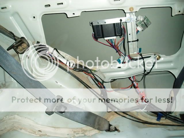
here is a pic showing the stealth install i did, you can see the DEI black shock sensor to the very left.
i have my au94tm sensor under my e-brake console, no pic... looks good eh
and the backup battery is hard to see but its mounted along the section where my grounds are connected.
here is a pic showing the stealth install i did, you can see the DEI black shock sensor to the very left.
i have my au94tm sensor under my e-brake console, no pic... looks good eh
and the backup battery is hard to see but its mounted along the section where my grounds are connected.
09-22-2007, 08:19 PM
#9
Honda-Tech Member
iTrader: (1)
Join Date: Oct 2005
Location: 99 probs but a stolen car aint 1, ca, cerritos/fullerton
Posts: 9,716
Likes: 0
Received 3 Likes
on
3 Posts
I am allways right I would cover both sides of the car with dyna-matt to help cover everything  Not bad for a rookie
I would cover both sides of the car with dyna-matt to help cover everything Not bad for a rookie
09-22-2007, 10:31 PM
#10
Honda-Tech Member
I am very impressed. Thank you for validating my work.
Fix the diagram so I can add it to the FAQ. With your permission I'd like to add it to my site with full credit of course. My only request is that you make the width 450px (or smaller).
Fix the diagram so I can add it to the FAQ. With your permission I'd like to add it to my site with full credit of course. My only request is that you make the width 450px (or smaller).
09-23-2007, 08:58 AM
#12
* B A N N E D *
Thread Starter
Join Date: Jun 2007
Location: salt lake city
Posts: 852
Likes: 0
Received 0 Likes
on
0 Posts
one question, whenever i trigger one of the sensors three times my LED doesnt turn off when i disarm the car (blinks two or three times in sequence).... i dont have any ignition harnesses connected (doing fuel cut only) i heard i need to hook the ignition up in order to reset the system?
btw i have waited over an hour and it doesnt turn off, i end up having to cut power to the alarm... what are my options i still want to keep the LED but i dont want to keep reseting the system.
btw i have waited over an hour and it doesnt turn off, i end up having to cut power to the alarm... what are my options i still want to keep the LED but i dont want to keep reseting the system.
09-23-2007, 11:45 AM
#14
* B A N N E D *
Thread Starter
Join Date: Jun 2007
Location: salt lake city
Posts: 852
Likes: 0
Received 0 Likes
on
0 Posts
<TABLE WIDTH="90%" CELLSPACING=0 CELLPADDING=0 ALIGN=CENTER><TR><TD>Quote, originally posted by 94_DC4 »</TD></TR><TR><TD CLASS="quote">You did not connect the ignition input for the alarm. You have to use the yellow wire from the ribbon cable. </TD></TR></TABLE>
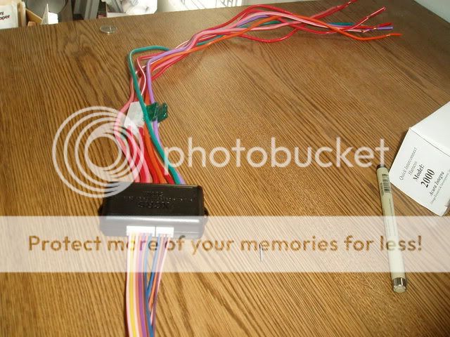
so should i cut the end off of the XCRS plug and connect the single yellow wire to ignition 12v?
or do i need to use the entire XCRS module? need answer asap.
so should i cut the end off of the XCRS plug and connect the single yellow wire to ignition 12v?
or do i need to use the entire XCRS module? need answer asap.
09-23-2007, 12:38 PM
#16
* B A N N E D *
Thread Starter
Join Date: Jun 2007
Location: salt lake city
Posts: 852
Likes: 0
Received 0 Likes
on
0 Posts
and run it up to ignition 12v? im going to have to extend it is this alright?
pin1: pink/white programable (-) ign2/acc2 relay turn on
pin2: yellow (+) ing. input to alarm
pin3: pink (-) 200ma ign elay turn on
pin4: orange (-) 200ma starter relay turn on
pin5: purple (-) 200ma starter relay turn on
pin6: orange/black (-)anti grind
pin7: (-) 200ma status output
Modified by akunamatta at 1:53 PM 9/23/2007
09-23-2007, 01:13 PM
#17
Honda-Tech Member
Yeah. You will have to extend the yellow wire . You do not need any of the other wires. You can just de-pin them.
09-24-2007, 08:21 PM
#22
* B A N N E D *
Thread Starter
Join Date: Jun 2007
Location: salt lake city
Posts: 852
Likes: 0
Received 0 Likes
on
0 Posts
<TABLE WIDTH="90%" CELLSPACING=0 CELLPADDING=0 ALIGN=CENTER><TR><TD>Quote, originally posted by 94_DC4 »</TD></TR><TR><TD CLASS="quote">No problem. </TD></TR></TABLE>
im going to test out the range tomorrow so check back and ill update the thread
</TD></TR></TABLE>im going to test out the range tomorrow so check back and ill update the thread
10-12-2007, 09:32 PM
#23
* B A N N E D *
Thread Starter
Join Date: Jun 2007
Location: salt lake city
Posts: 852
Likes: 0
Received 0 Likes
on
0 Posts
alright finnally got around to testing the alarm out, the working range was approxametley one mile (according to an odometer) the only thing was it took about 10 seconds to reach the remote once the alarm was triggered... anyways im satisfied and everything is still working fine.
one question though, ive only had the alarm setup for a little over 2 weeks and my battery on my SST remote is already showing 1/4 battery left... are you guys going through batteries this often?
one question though, ive only had the alarm setup for a little over 2 weeks and my battery on my SST remote is already showing 1/4 battery left... are you guys going through batteries this often?
10-13-2007, 09:05 AM
#25
* B A N N E D *
Thread Starter
Join Date: Jun 2007
Location: salt lake city
Posts: 852
Likes: 0
Received 0 Likes
on
0 Posts
<TABLE WIDTH="90%" CELLSPACING=0 CELLPADDING=0 ALIGN=CENTER><TR><TD>Quote, originally posted by wrx-killer-Sti-eater »</TD></TR><TR><TD CLASS="quote">Don't use the one it came with. Its just to get you started</TD></TR></TABLE>
what do you use, like a lithium high tech one? would it affect range at all having a better battery?
what do you use, like a lithium high tech one? would it affect range at all having a better battery?