
CLM Project 240sx
 11-22-2010, 12:50 AM
#1
Honda-Tech Member
Thread Starter

Join Date: Sep 2009
Location: Toronto
Posts: 84
Likes: 0
Received 0 Likes
on
0 Posts
Hey Boys & Girls,
Nov 21st 2010

Now that you have seen the starting grounds of what I hope of a really good project I would like to post up some of the recent fabrication tools I picked up in the last couple months.
I picked up a few nice things to help me do almost anything.
JD Square Model 32 Bender [Bought this during my last build]

Precision Tig 225 & Cool-Arc 40 Water Cooler [Bought tig welder after last build, water cooler is new addition]

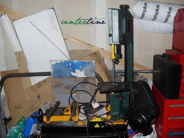
Metal Bandsaw
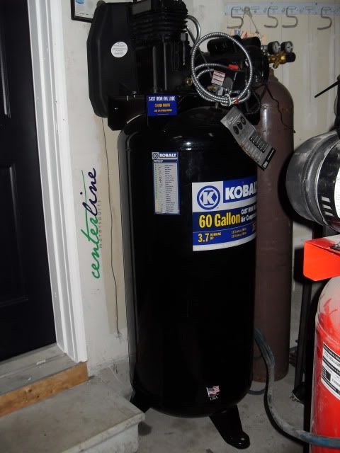
60 Gallon Compressor
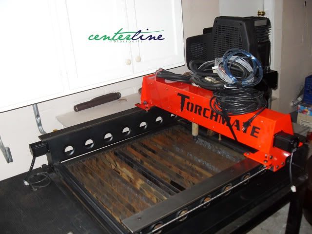
Torchmate Plasma CNC Machine & Hypertherm Powermax 45

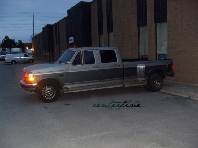
The best addition to everything was the pickup of my new [well old] Truck
Ford F350 Crewcab Diesel Dually [Getting some paint and wheels next spring]
That’s all I got for today! I should have more posted soon.
STAY FRESH EVERYONE!
I would like to start by saying I have been lurking around the site for a bit since my last big build. I haven’t been very active on the forums, but have always been looking for a new challenge [Project]. Some might question my ethics as to why another 240sx….or why didn’t I just keep the original one I had with the 2JZ. I must say I did try and find a new platform to work with and move away from the older chassis of the 240sx, but the problem that came from that was I couldn’t really find anything that interested me. I really wanted to get into an evo, but starting price plays a really big factor in everything and it’s always nice to have a very basic base as a starting point.
The plan for this build thread will be the same as the last one. I plan to keep everything up to date and make sure to post everything in orderly fashion just as the last one. I know many of you may think how can I possibly top the last build….well that’s a good question, but when it comes down to it there is always something that could be done better than the last one. I already have a major parts list of things I need to do, fabricate, buy and whatever else could possibly be done. The only slight difference between this build compared to the last one is I plan to build, fabricate as much as I can in-house and have very limited out sourced.
I hope with all my new and interesting fabrication equipment I’ll be able to make just about anything. It may all seem like a big task to complete, but with the help and support of friends and family anything is possible.
So, let’s get started.Nov 21st 2010
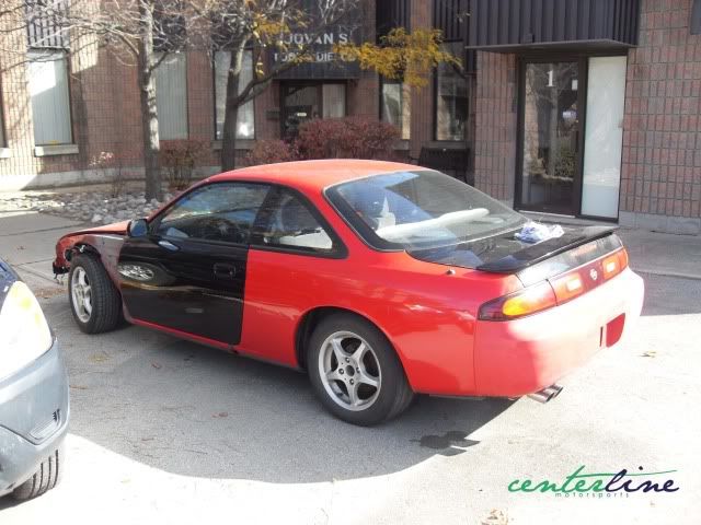
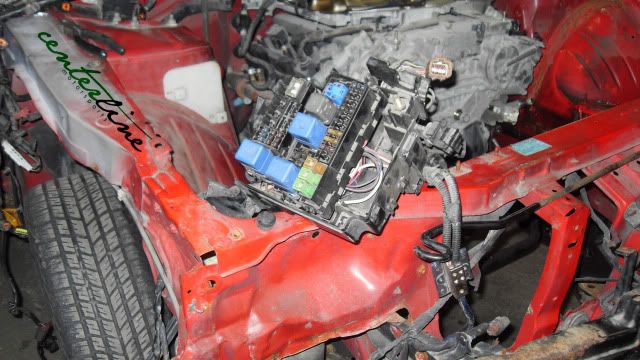
The day begins as I pickup my new project off my buddy Stefan [Foot]. He had plans of building a nice street car from this very clean chassis, but due to circumstances he had to bail. I personally think he couldn’t have sold it to a better person  . Now that we have some history out of the way we move onto the car. The car itself has a very small rust spot on the driver side rocker and some light rust in the engine bay, which I would say is typical to most 240sx. To my luck this was a Texas car so the frame rails are mint, but doesn’t really matter since its unibody. The only downside to the whole car is that its auto so it gives me some work to swap it over, but nothing to major compared to everything else that needs to be done.
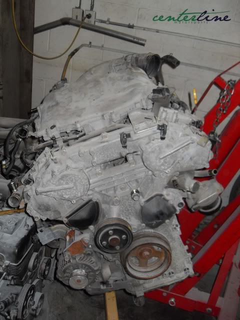
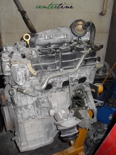
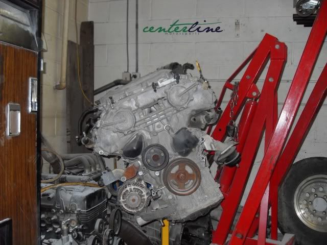
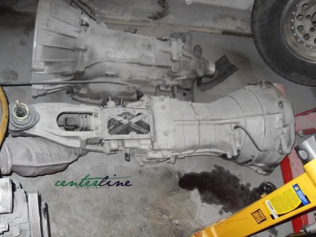
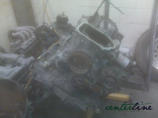
. Now that we have some history out of the way we move onto the car. The car itself has a very small rust spot on the driver side rocker and some light rust in the engine bay, which I would say is typical to most 240sx. To my luck this was a Texas car so the frame rails are mint, but doesn’t really matter since its unibody. The only downside to the whole car is that its auto so it gives me some work to swap it over, but nothing to major compared to everything else that needs to be done.Motor selection took some time to decide. I had been juggling the idea of this whole project for quite some time and it was all to be completed with a VQ35DE. The motor itself is not the most appealing motor setup to ever come from Nissan, but I thought this time I would keep it to a Nissan power plant. There were many more possibilities as to Nissan motors, but I just couldn’t pass the price I got for a complete motor set with only 50,000km. The next big question is to twin turbo or rock it one hundred percent naturally aspirated. I have been leaning more to one than the other, but I’ll be keeping that a secret until I reach that step in the build progress. I ended up disassembling some of the motor setup and didn’t have pictures of it all complete with everything on it, but in other news I ended up finding a nice 6 speed transmission for a really good price.
Many of you may be saying to yourself PICTURES!!!! So enough of this reading how about some pictures!!! Now that you have seen the starting grounds of what I hope of a really good project I would like to post up some of the recent fabrication tools I picked up in the last couple months.
I picked up a few nice things to help me do almost anything.
JD Square Model 32 Bender [Bought this during my last build]
Precision Tig 225 & Cool-Arc 40 Water Cooler [Bought tig welder after last build, water cooler is new addition]
Metal Bandsaw
60 Gallon Compressor
Torchmate Plasma CNC Machine & Hypertherm Powermax 45
The best addition to everything was the pickup of my new [well old] Truck
Ford F350 Crewcab Diesel Dually [Getting some paint and wheels next spring]
That’s all I got for today! I should have more posted soon.
STAY FRESH EVERYONE!
 11-22-2010, 11:02 PM
#7
Honda-Tech Member
Thread Starter
Join Date: Sep 2009
Location: Toronto
Posts: 84
Likes: 0
Received 0 Likes
on
0 Posts
Trending Topics
11-22-2010, 11:02 PM
#8
Honda-Tech Member
Thread Starter
Join Date: Sep 2009
Location: Toronto
Posts: 84
Likes: 0
Received 0 Likes
on
0 Posts

 12-01-2010, 08:03 AM
#11
Honda-Tech Member
Thread Starter
Join Date: Sep 2009
Location: Toronto
Posts: 84
Likes: 0
Received 0 Likes
on
0 Posts
Nov 29th 2010
Back Again!
2) The oil capacity of a dry sump can be as big as you want. The tank holding the oil can be placed anywhere on the vehicle.
3) In a wet sump, turning, braking and acceleration can cause the oil to pool on¬ one side of the engine. This sloshing can dip the crankshaft into the oil as it turns or uncover the pump's pick-up tube.
4) Excess oil around the crankshaft in a wet sump can get on the shaft and cut horsepower. Some people claim improvements of as much as 15 horsepower by switching to a dry sump.
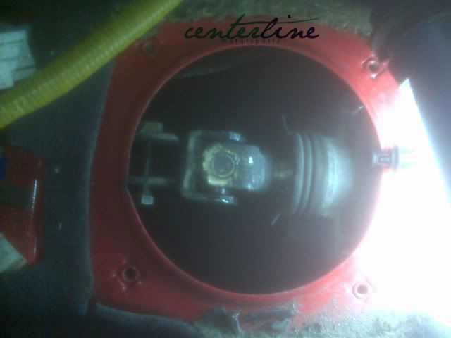
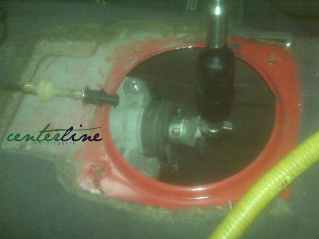
Anyways Picture time, sorry about some cell phone pictures.


Until Next Time!
Back Again!
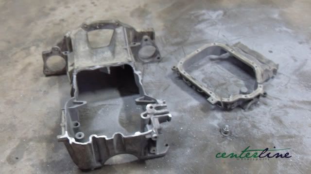
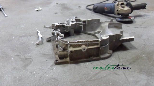
I really don’t have a big update, but I do have some ideas in the works which I will share with you later in the post. Anyways I ended up heading up to the shop and flipping the motor over to get started on ripping off the pan. On a side note always remember to drain all fluids to a dry state before flipping the motor over. Once I removed the lower pan I moved forward onto the upper pan. The upper and lower pans itself wasn’t too hard to remove.
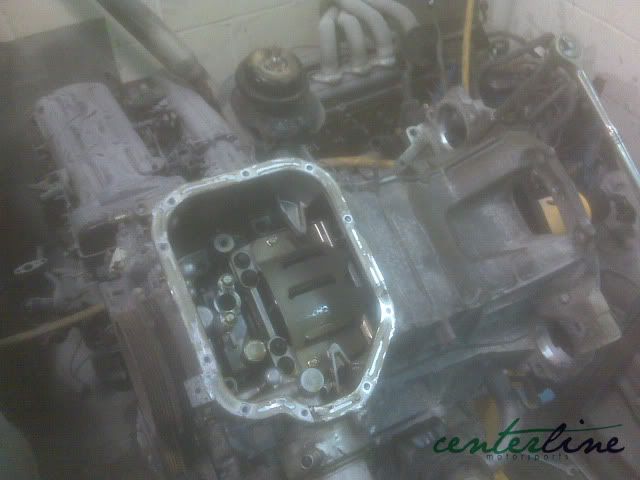
Once they were removed I went forward and removed the oil filter and the cooler for the filter, which was fairly simple. Now that the pan was off, I covered the block with cloth as I spend some time with the upper oil pan. The pan has to be modified to work with the dry sump setup I will be doing. The benefits of a dry sump oil system are as follows…
1) Dry sump does not need to have an oil pan big enough to hold the oil under the engine, the main mass of the engine can be placed lower in the vehicle. This helps lower the center of gravity and can also help aerodynamics2) The oil capacity of a dry sump can be as big as you want. The tank holding the oil can be placed anywhere on the vehicle.
3) In a wet sump, turning, braking and acceleration can cause the oil to pool on¬ one side of the engine. This sloshing can dip the crankshaft into the oil as it turns or uncover the pump's pick-up tube.
4) Excess oil around the crankshaft in a wet sump can get on the shaft and cut horsepower. Some people claim improvements of as much as 15 horsepower by switching to a dry sump.
I took the above 4 quotes from How Stuff Works to make my life simple. Once the pan itself is modified to fit the block and engine is placed back into the engine bay I can move forward to check clearance between all the factors that come into play. The main clearances that I would be watching for are the pan and where it sits in reference to the sub frame, also where the engine sits in reference to the hood and strut towers. Once I finish up with that I can move forward with the other aspects of the build, but the idea for the pan doesn’t just stop with the modified oil pan.
Since I recently bought the nice CNC setup, I plan to work with a friend to create a billet version of the oil pan. Once modified to fit my setup should in theory work for the 350z/G35 guys. I know there are products on the market like the Dailey Engineering dry sump, but the price tag of $5700 USD doesn’t really sound that great to me. The Dailey setup is amazing and most likely worth every penny, but I’m hard headed. Some might say why even spend unnecessary time building a billet pan when a modified stock one will work just fine, but I rather just try and take that next step and being hard headed.
“Sometimes ideas that sound stupid turn out to be examples of the kind of out of the box thinking that produces amazing results.” (NASA Blog “No Stupid Ideas”)Anyways Picture time, sorry about some cell phone pictures.
Until Next Time!
12-04-2010, 08:05 PM
#13
Honda-Tech Member
Thread Starter
Join Date: Sep 2009
Location: Toronto
Posts: 84
Likes: 0
Received 0 Likes
on
0 Posts
 12-07-2010, 09:37 PM
#15
Honda-Tech Member
Thread Starter
Join Date: Sep 2009
Location: Toronto
Posts: 84
Likes: 0
Received 0 Likes
on
0 Posts
I'm looking at a stance 3-way shock setup, but will see what happens when it comes down to it. i would really like to keep the idea of a 3-way shock. The idea behind this car is more of a circuit car, but try and pull the whole street car at the same time. Main plan is to attended some of the Redline events.
12-07-2010, 09:39 PM
#16
Honda-Tech Member
Thread Starter
Join Date: Sep 2009
Location: Toronto
Posts: 84
Likes: 0
Received 0 Likes
on
0 Posts
Dec 6th 2010
OIL PAN UPDATE!
Anyways enough of all this B.S. let’s move onto the pictures!

Stay Posted!! Subscribe!!
OIL PAN UPDATE!
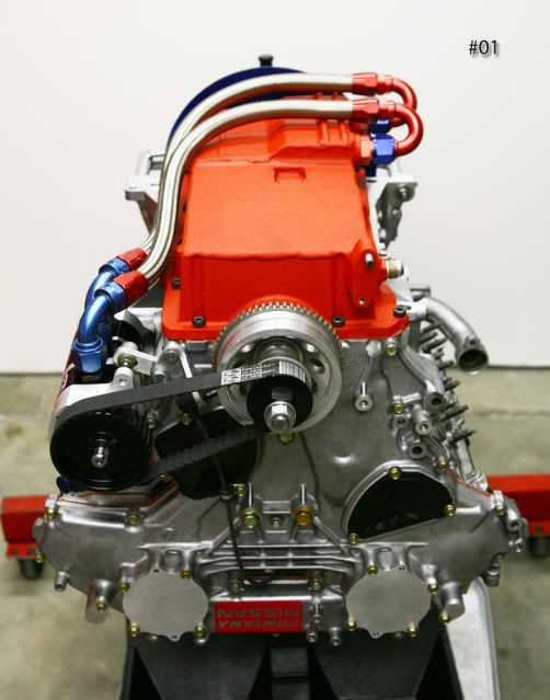
Ok, let me start by saying I have been slacking hard! The pan has been sitting on my garage floor for about a week now and I haven’t done anything with it up until yesterday. Now, that doesn’t mean I haven’t been doing research. I decided to take a look over at Fontana Nissan and their work on the 350z/VQ35DE. While I was looking around their build I came across their previous dry sump setup [Ref #01].
The setup you see below is very similar to the setup I will be running, which is a great setup and many before me have been running from street cars to full blown race cars. What I’m doing is nothing new by any means, but at the same time even though my setup may be conventional it’s also getting that extra kick with the billet pan. Below I have provided a sample of a conventional dry sump setup. [Image From Moroso Website]Anyways back to Fontana’s setup, their initial design was great, but I feel I would change one design aspect of it. As you can see in the picture below [Ref #01] they have the rear of the pan setup to feed back into the pump, which will work just as good as any other setup, but I would of supplied fittings on the left and right of the pan to provide a better flow of return and not focused only onto one side.
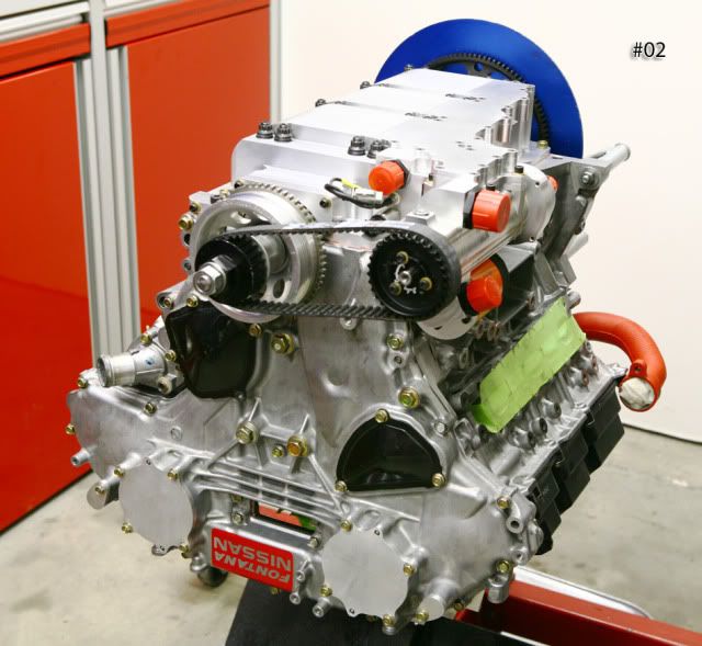
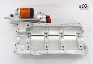
The setup on the left and right would also provide better return when cornering left or right which I think would be a better flowing system overall. I could be completely wrong, but I’m just looking at it from other designs I have seen and looking at it from the cornering aspect of it all. They had a more than solid design point with their setup, but they had issues with oil pressure not being where they wanted it to be. They then moved forward and contacted Dailey to develop the pan setup they have now. [Ref #02]
I now see why the Dailey setup itself would be fully worth every cent. If you reference to picture #02 you can see it’s fully machined out of billet aluminum, but that’s not the only key of the pan. Yes, the pan made out of billet does add a great amount of strength to the motor, but seeing how Dailey incorporated the 4 bolt mains and a whole new girdle setup is a big plus. This setup will also help keep the pan even closer to the block, which will result in an even lower center of gravity. The girdle setup provides an even return from every section of the block.
The setup of the girdle still differs from OEM design which I'm keeping, but like I said above works great none the less. The pan also keeps OEM specifications on how the oil feed is setup to feed the block, which u can see in the picture below. This feed setup is a great plus and keeps the setup fairly simple from a design point. The pan also incorporates the pump into it all to remove the need for all the lines a conventional dry sump setup may use, which would also stop the chance of possible leaks from the system. Oil leaks are never a good leak someone wants to have so keeping it simple again and removing the need for lines is a big plus any way you look at it.
The Dailey setup also incorporates the oil filter, which also removes the need for lines once again and also keeps everything in a nice compacted setup. The Dailey pan is a superior setup to anything on the market and is proven to work. Now, my pan will be in a league of its own as it will not compare to the Dailey setup, but the one thing that I really plan to incorporate into my setup is keeping the OEM location on the oil feed and putting a supply fitting on the outside. This design aspect will be similar to the Dailey pan, but the complexity of the pan will be nowhere near their design.
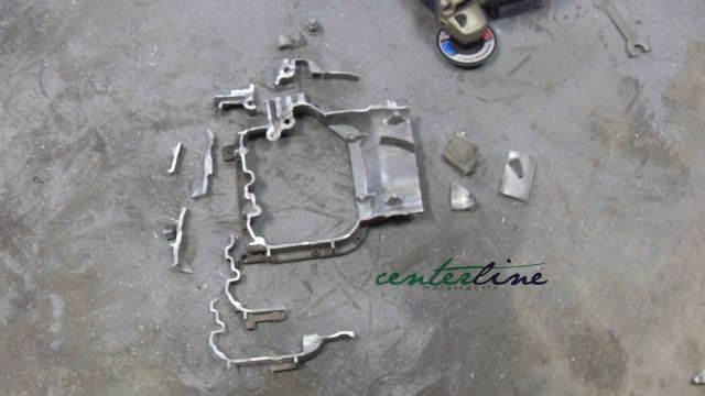
Some of you may have also noticed on the Dailey setup and Fontana’s original design they both removed the bottom mounting section of the transmission and starter section off the original pan design. The reason is it provides a better and a less complex design of the oil pan. I also had a discussion with my step father regarding the rear section on the pan and he concluded to tell me all it mainly does is provide the transmission from trying to twist from torque a motor may make, but could be ran without the lower portion as you would need high torque. This may seem like its very important, but a solution to that may also be to make a bracket to support the lower bolts and the starter. The other option could also be is to make a plate or adapter plate to incorporate the lower bolts and starter all into one which I’m sure if done with steel, would be very strong and could be done with less thickness than if done with aluminum.
I know I may have bored a lot of you with what some may think as useless info, but looking closer into the Dailey setup and other conventional setups help provide me with a even better understanding of what I must incorporate or can remove from my dry sump system and pan.
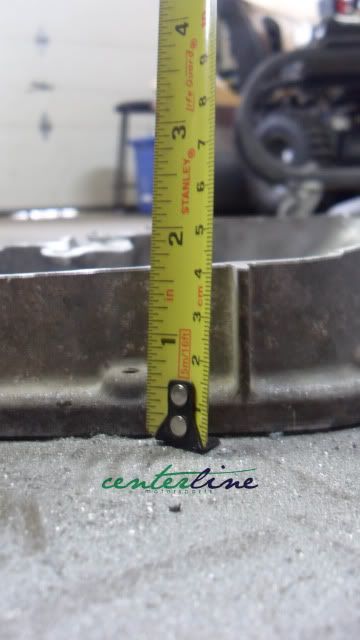
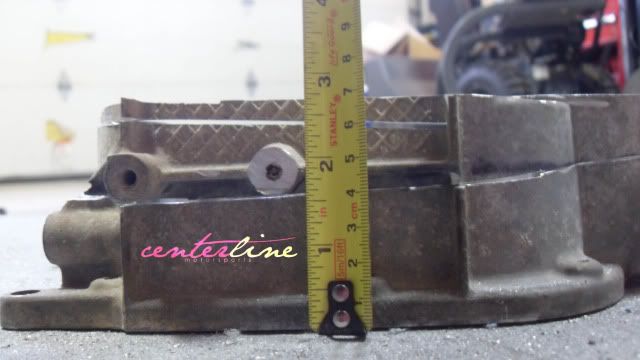
Now, let’s continue with the build. I forgot to take total height of the pan complete which was a total brain fart on my part, but that doesn’t mean I couldn’t take a guess on the measurements I do have so far. Below you can see the section of the pan I first cut and the second section I cut after seeing I had more clearance to play with. First section came in at 1 5/8”; second section came in at 1 1/8” which gave me a total of 2 3/4” cut from the pan not including the lower section of the pan which incorporates the drain. I would say the lower pan would give me about another 2” of clearance to be on the safe side.
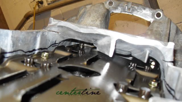
If we take all current measurements, it would give us a total of 4 3/4” of savings in height from the original pan design. I really think it will help the improvement of the cars performance with a lower center of gravity of almost 3”-5” compared to where it might sit in other developed swaps on the market. I’m in no way trying to knock the development of the other swaps on the market as I’m sure they had their own individual R&D. As you can see in one of the pictures below you will notice clearance of the pan to the girdle before I decided to remove more from the pan to get my total clearance of almost 5” from original pan height. I really had more room to play with, which is very noticeable in that picture.
My current plan of attack is to completely cap off the pan with a piece of aluminum and tack it in a few spots for the trial fitting of the motor. I also plan to have the motor sitting in the engine bay and mocked up where I would like it to fully sit by Sunday afternoon. Now if I can get as far as getting the engine in the location I want it, then that will let me move forward with some test engine mounts. I also plan to make some engine mounts using SolidWorks and the help on a buddy to develop some custom one off mounts based on the original test design.
Anyways enough of all this B.S. let’s move onto the pictures!
Stay Posted!! Subscribe!!
12-10-2010, 01:23 PM
#18
Honda-Tech Member
Join Date: Jul 2004
Location: Chicago IL, Waukesha WI, USA
Posts: 480
Likes: 0
Received 0 Likes
on
0 Posts
Are you fabbing your own motor mounts or using a mount kit? I don't understand how this will lower the center of gravity unless the engine position is also being moved.
12-10-2010, 03:45 PM
#19
Honda-Tech Member
Thread Starter
Join Date: Sep 2009
Location: Toronto
Posts: 84
Likes: 0
Received 0 Likes
on
0 Posts
i'm making my own engine mounts, which will let me drop the pan almost on the subframe and also looking into making my own moly subframe that brings everything a bit lower.
12-14-2010, 06:10 PM
#21
Honda-Tech Member
Thread Starter
Join Date: Sep 2009
Location: Toronto
Posts: 84
Likes: 0
Received 0 Likes
on
0 Posts
Dec 13rd 2010
Hello Once Again!


Hello Once Again!
I sit here with a blank page before me and “Kaskade – Fire In Your New Shoes” in the background playing away! I really wasn’t feeling the big update today, but I couldn’t sit here and not have an update for everyone.
I had the keys to the shop over the weekend. One would think that I should have got a retarded amount of work done, but that was the total opposite. Now, don’t get me wrong with what got done, but I’m also not very happy because I could have got a lot more done. Saturday was mostly a write off! Mainly due to distractions and the fact I had to leave early. Most of the work posted in this update was all done on Sunday where I spent most of the day alone.
Anyways…let’s get started.
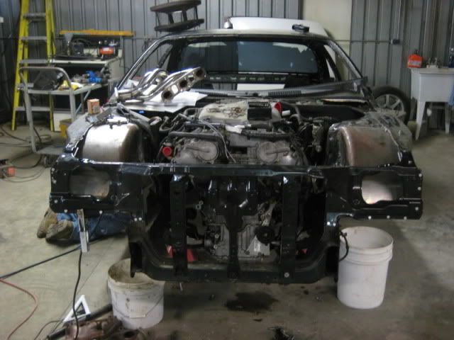
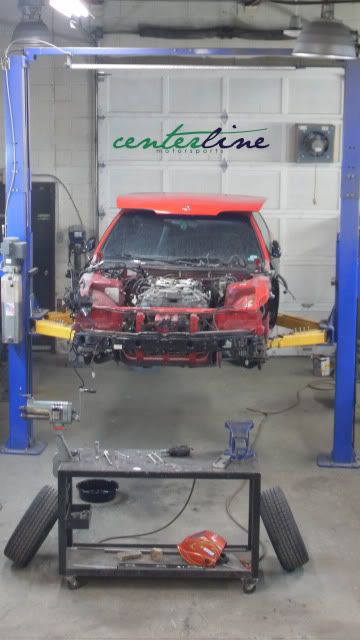
I got to the shop Saturday morning and first thing first was put the car on the hoist. Checked over the car and removed the hood to get cracking on the car. The motor was removed the first day I took ownership of the car, but completely forgot to take pictures during that process, but I’m sure most don’t mind. So, I have an empty engine bay and a motor and transmission package just waiting to go into a new home. I ended up just doing exactly that!!
Now, I could end my post here and call it a night, but that’s just not my fashion…even though I am in no mood to completely write this update. “THE SHOW MUST GO ON”
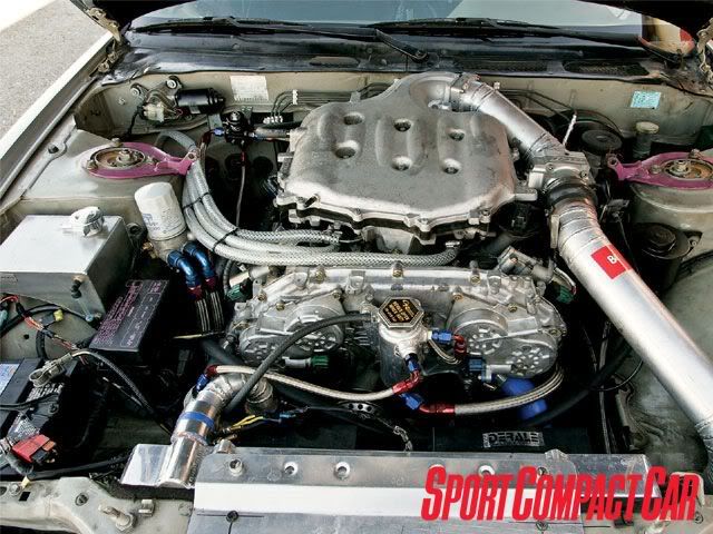
Let’s continue on this endeavor. I was completely reminded on my last post that I posted I wanted to bring the motor to a “Lower center of gravity” hence dropping the motor lower than “OEM” KA location or to relevance of other swaps like this. To be completely honest….I’m not even really sure if I fully succeeded at that task, but let’s say I’m not out for the count just yet! I decided to do some research around the net looking at some of the VQ35DE swaps and see how high the manifold sits and where the cylinders line up in reference to the towers.
Let me first start by saying I am in no way trying to say that these swaps are wrong or hating on anyone’s work.
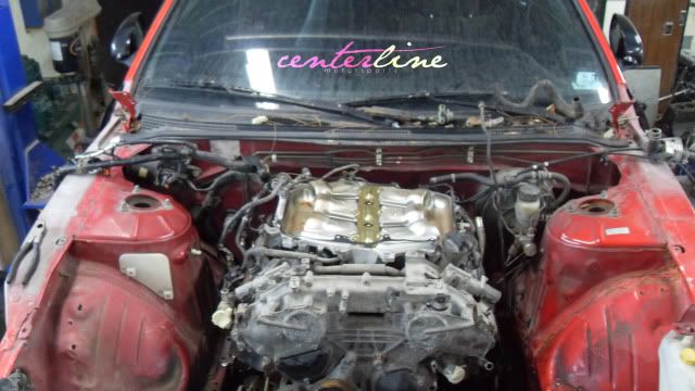
Ok, so if you notice the pictures below you will also notice how high the motor “intake manifold” sits. The hood might come in contact with the intake manifold and the inner ribs of the hood would have to be cut out to remedy this problem. This height is not too much of an issue if you’re only really cutting out the inner ribs of the hood, but I feel it would bug the **** out of me! I looked over it again and thought to myself, what if you were to upgrade the throttle body to a 90mm….I see many issues with that! I don’t see it fitting unless one was to make an adapter plate that would extend the throttle body further into the engine bay. Anyways, that’s a totally different topic in itself.
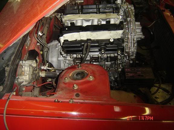
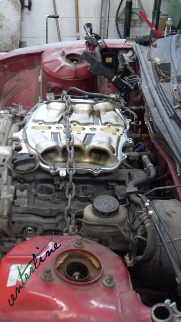
I clearly don’t have the intake manifold on my motor due to it just didn’t fit because of the placement of my motor. I also completely forgot to take some measurements of the difference of change compared to how the motor would sit with the intake manifold on, but I’ll defiantly remember to get some next time. Technically I can’t really prove my motor is any lower until I fit up the upper intake manifold to the motor and see where I’m sitting in comparison to the other swaps out there.
Next, I took a look at the cylinders in reference to the strut tower. It might be hard to tell from the pictures above, but in the picture below seems like the motor sits between cylinder 2 and 3. I’m sure the swap works just as good, but I wanted to keep most of the motor mass behind the towers. If you look below you can compare both pictures below. From looking at both, my swap looks more like its sitting on cylinder 1 and 2 which I hope will give me a totally better weight balance.
I don’t have any cold hard evidence to prove that the weight balance is affected with my motor being back more, but I do have a plan to try and remedy that. I called up my buddy and asked him if I could use his scales. Scales! Yes scales. I hope to have the car weighted/cornered weighted to see where it’s sitting in its current state. This I hope should give me a better understanding on where the car sits as in weight to the Front Left, Front Right, Left Rear, Right Rear and also Front to Back weight. This will also help give me a better understanding on where things should be placed, but I also plan to keep updating weight changes to keep understanding where weight changes need to occur or placement of parts should be.
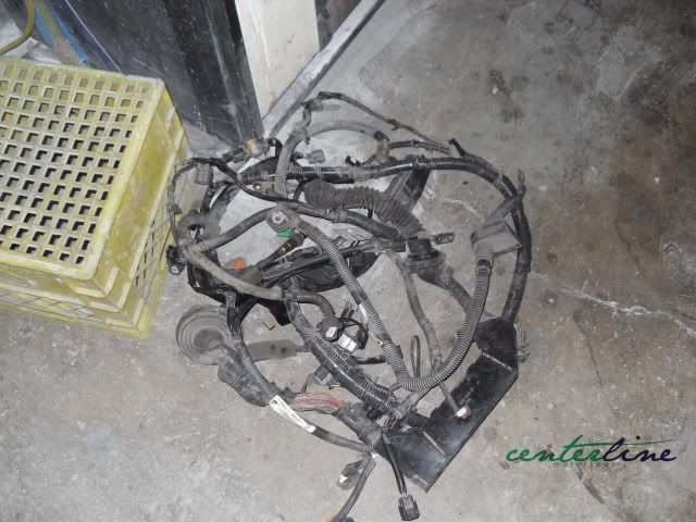
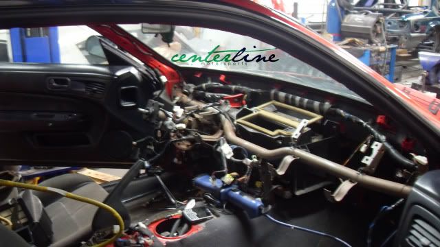
I moved forward from all the current things brewing in my head and decided to focus my attention on removing the dash, chassis harness and engine harness from the original engine that was in the bay. I did the same process on the last project, but all in all it took quite some time to remove everything properly. I do plan to relocate my chassis harness under the dash again, but I also plan to redo my complete harness “Raychem” style which some lovely “Mill-Spec” connectors into the firewall. I not only plan to do this for the chassis harness, but also the engine harness too.
It’s a long and pains’ taking process, but someone’s got to do it! I now have the harness here at home with me and plan to get started on it soon. It truly sucks not having the car here at home with me, but once spring hits I hope to bring it home and get the ball rolling even more.
Once all that was completed I moved to the last thing for the weekend which was the shifter! First thing I decided to check was where the shifter was place, but once again I forgot to take a picture. Anyways I took it out and modified it like the other swaps I have seen, but like you see below when the shifter is in 2nd, 4th and or 6th gear it sits too far back. Then I decided to try 1st, 3rd and 5th its closer, but still isn’t going to work for me. I then decided to re-drill the pin mounting hole on the main arm off the transmission so I could rotate it 90 degrees to allow me to use it as the shifter assembly.
This setup does work, but the gear ratio becomes retard tight and makes it almost difficult to land it in neutral. I need a solution….I thought about two possibilities and one involves making the shifter itself taller which could end up working in my benefit or possibly design a mechanism that incorporates the u-joint design that’s included into the shaft assembly. I have a bit of thinking to do and even a bit of research to perfect some sort of design.
Anyways I think I have written more than enough for one night, but I’ll be sure to have some more updates soon and maybe not so much information jammed into them. I’ll leave you with some more pictures I took that I haven’t included in the post so far. Also i would like to thank the wayne, vic and tiger for the help dropping in the motor!
Enjoy!! 
Thread
Thread Starter
Forum
Replies
Last Post