When you click on links to various merchants on this site and make a purchase, this can result in this site earning a commission. Affiliate programs and affiliations include, but are not limited to, the eBay Partner Network.
DIY ECU/PCM Replacement (no honda re-flash required)
Hey there Honda people,
I recently had to repair a 7th gen civic that had the alternator bolts break off when the engine was running causing the all too common issue of frying the ECU/PCM. When I had finished re installing the alternator the car was stuck in limp mode (stalling out, no power, PGM-FI relay clicking, no tach, and no com with ECU.
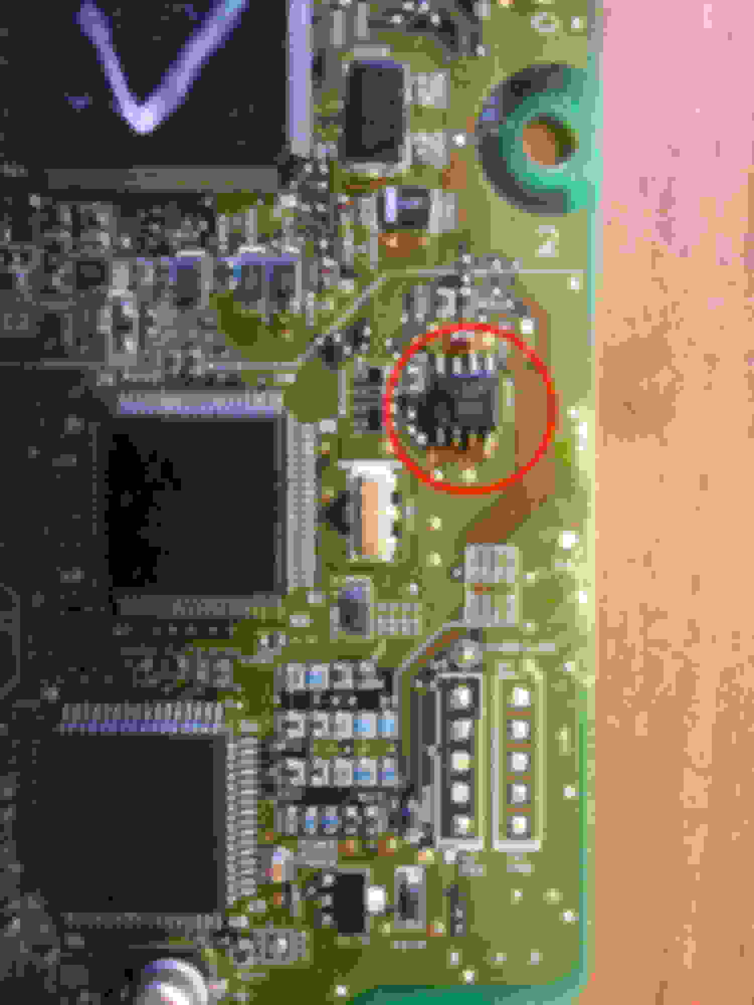
To fix this, grab yourself a used ECU. I went to my local U-Pull yard and got one for $40. Then remove the fried ECU and open it up. On the side of the board opposite the connectors there is a small EPROM chip labeled IC240. Remove this from the board and solder it in on in the new ECU. Next, de-solder the large green chip with 16 legs labeled HIC340 and solder it onto the new ECU. Now I'm not sure if that step is necessary (I thought this might have been part of the immobilizer) but it worked for me. Now just install the new ECU with the transferred parts into the car and it will be as good a new.
For only $40 and the time spent soldering, the car is back to normal and the best part is that you don't have to get towed to the stealership to have the car reprogrammed.
Re: DIY ECU/PCM Replacement (no honda re-flash required)
Originally Posted by 7rrivera7
Excellent - thanks for sharing!
No problem. I just wanted to share with people an alternative solution to the problem. I have seen the question of how to replace the ECU answered with "your only option is having Honda program it" way too often. There is alway another way. Actually I can think of a few more ways too but my method is by far the least expensive and fairly easy if you can solder or know someone who can.
Re: DIY ECU/PCM Replacement (no honda re-flash required)
Because having problem with my immobilizer right now...did replaced the immo unit receiver but it think it needs to be reprogram...sending it too dealership is a lot of cash...if i can remove the immo chip...
Re: DIY ECU/PCM Replacement (no honda re-flash required)
[QUOTE=miketunstall;51246085]Hey there Honda people,
I recently had to repair a 7th gen civic that had the alternator bolts break off when the engine was running causing the all too common issue of frying the ECU/PCM. When I had finished re installing the alternator the car was stuck in limp mode (stalling out, no power, PGM-FI relay clicking, no tach, and no com with ECU.
To fix this, grab yourself a used ECU. I went to my local U-Pull yard and got one for $40. Then remove the fried ECU and open it up. On the side of the board opposite the connectors there is a small EPROM chip labeled IC240. Remove this from the board and solder it in on in the new ECU. Next, de-solder the large green chip with 16 legs labeled HIC340 and solder it onto the new ECU. Now I'm not sure if that step is necessary (I thought this might have been part of the immobilizer) but it worked for me. Now just install the new ECU with the transferred parts into the car and it will be as good a new.
For only $40 and the time spent soldering, the car is back to normal and the best part is that you don't have to get towed to the stealership to have the car reprogrammed.
This Works!!!
I have a 2003 Civic EX 1.7L 5-speed, and my ECU fried due to loose alternator bolts, exactly as described above. No tach, no temp gauge, wouldn't link to a code reader, running in limp mode, PGM-FI relay clicking at startup, etc. I googled in search of a fix, and found this thread. It made sense. I used a voltmeter to verify that in the diagnostic port, pins 4-5 were ground and pin 16 was battery voltage. So it wasn't a bad diagnostic port connection. HAD to be the ECU.
I bought a used ECU on e-Bay (I got one with the same number, 37820-PLR-L06 in my case), and I switched the 8 pin EEPROM chip (the L56R chip) shown in the photo above. The chip has a little half-moon shaped groove on the left end (as oriented in the picture), and you must install the replacement chip from your old computer in exactly the same orientation. I did NOT change the green vertically mounted package described above. BINGO, it works great!!!
If you're experienced with reworking surface mount circuit boards, then kindly ignore my advice below and do what works for you. And then share, and educate me! For everyone else, until a professional offers better advice than my mid-level amateur experience level, here's a good starting point. It'll at least get you in the ballpark, and give you a reasonably high chance of success for this particular job.
To remove the chips from their respective boards, and to re-solder my old chip to the new board, I used a rework station I bought from Digikey for $150. Temp set at 380C, airspeed set on 4. I used the medium sized tip that came with the kit (tip was slightly larger than the chip). I held a little tension on the chip using a good pair of electronics tweezers (also purchased from Digikey), held the hot air nozzle close to the chip, and it popped right off after maybe 5-8 seconds. I did briefly preheat the chip at a 200C setting, to avoid excess thermal shock (not sure if that's absolutely necessary; you don't have to worry as much with small chips as with the larger arrays). I don't even want to think about trying to use an industrial heat gun from Harbor Freight, as I've read about on another forum. Not saying someone couldn't pull it off, covering the board with aluminum foil and cutting a hole around the component you're working on, but your chances of catastrophic failure are exponentially higher. WAY too much heat over way too much area. Like using a 12 gauge shotgun to kill a housefly, likely destroying everything else in the area, rather than using a pneumatic salt gun or a fly swatter. So when someone says to use a heat gun for this kind of work, think rework station. It's technically a hot air type heat gun, but with precise temperature and airflow control for electronics. If you're not sure which one you need, the tech people at Digikey will help you. You want a quality unit with accurate temp controls. This is not the time to skimp and low-buck it!
If you feel the need to use solder braid to clean up any excess solder from the board after removing the chip, simply place the braid over the pads and roll the tip of the soldering iron over the braid. Do not slide the solder braid back and forth over the pads while pressing on it with the soldering tip; the heat and friction will wipe the pads right off the board and ruin it. Better yet, don't worry about cleaning up the pads, other than maybe wetting them with a little flux. Although the solder paste you use to solder your old chip to the new board contains a lot of flux.
I used a toothpick to dob a bit of solder paste (63/37 tin/lead solder, and yes, Digikey sells it) onto each of the pads, and placed my old chip onto the new board. It doesn't have to be positioned perfectly, just close (the legs of the chip must be on the correct solder pads, but they don't have to be perfectly centered). Set the workstation to 380C (same setting as removing the chip), and it melted the solder paste quickly. The paste turns from dark grey to shiny silver when it melts. The surface tension from the melted solder will perfectly align the chip onto the pads. Removed the heat immediately. Use a loop to double check your work (make sure all the solder paste melted, that each leg is neatly soldered to its pad on the circuit board, and that you didn't create any solder bridges between pads (caused by using too much solder paste).
If you've never done this before, do find a scrap circuit board (take an old electronic device apart, or something), and practice removing and re-soldering a similar sized component at least once or twice. Then, when you are comfortable with the process (and especially if your device still works after you removed and reinstalled something!), your chances of success with your ECU are very good!
Lead/tin solder has a lower melting temperature than lead-free solder, leaving a larger margin of safety between being hot enough to melt the solder and hot enough to damage a chip. And it has less chance of a bad solder joint. If you're a poor guy like me who can't afford failure and who doesn't do this every day, you need to stack every advantage in your favor. And having a higher rate of failure (thus throwing away more electronic garbage) using lead-free solder is worse for the environment than using an insignificant amount of lead/tin solder. In case you were worried. So use 63/37 tin/lead solder paste, and not the politically correct lead-free solder. Unless you REALLY know what you're doing, and even then you will likely prefer the leaded type.
Of course I used too much solder paste, and using a loop I could see two solder bridges between legs of the chip. I got out my soldering station, placed copper solder braid (Digikey sells that, too) on top of those areas, and pressed down on the braid with the soldering iron (the dial was turned to about 650 degrees F. Yes, my soldering station is calibrated in degrees Farenheit, and my rework station uses degrees Celcius. It isn't perfect, but I know what settings to use for each and I make it work.) The excess solder melted and almost instantly wicked up by capillary action into the solder braid, leaving a clean solder job underneath. You can feel the solder give way as it melts under the solder braid. Remove the heat immediately, so as not to damage components.
After that, I screwed on the cover and plugged the computer into my car. It runs perfectly now!!!
Although my Civic has been a very reliable car over the years, I am completely disgusted with how Honda did not electronically isolate the alternator from the computer. Not hard to do! You could probably use a high voltage Op Amp, a capacitive coupler, or an optoisolator among other likely options. It would probably cost an extra buck a car, and save $1,500 for the computer ($1050 for the computer, $160 to program it to match your key, $160 for the initial diagnosis to verify it really is your computer, and another hour's labor to remove the old computer and install the new one at my local dealer) plus the cost of a catalytic converter if you drive very far in limp mode before you get it fixed. So a dollar of responsible engineering to save the better part of $3,000 in repairs if you lose an alternator. I'm tempted to take apart my old alternator, observe the circuit design, and design my own isolation circuit to plug between the factory wiring loom and the alternator. Not even sure why the ECU has to control the alternator in the first place - what was wrong with having a dedicated regulator inside the alternator like the old GM 10si series?
A HUGE "Thank You!" to Miketunstall for posting this repair. I'm a hard working single father of two kids, and the information you posted made an invaluable difference for us this Christmas. I hope my experience adds to the body of knowledge that can help someone else.
Re: DIY ECU/PCM Replacement (no honda re-flash required)
thanks to both of you guys who wrote instructions on how to swap PCMs without having to get the dealer program immobilizer!
I'm about 98% sure I'm gonna have 2 replace the PCM in my Acura TSX and have been stressing about the programming part! I'd already decided I was def just gonna go to a pull your part place to get an ECU if it ended up being that but have heard horror stories of dealerships lying saying that only a new ECU would work!
so is there any further programming or anything required after switching the chip to get the car working? i guess what im tryna say is is the VIN programmed into that chip?
thx again!!
Re: DIY ECU/PCM Replacement (no honda re-flash required)
For my Civic, all the vehicle-specific information that needs to be programmed into a new computer, was contained in the 8 pin EEPROM chip I unsoldered from my old computer (other chips in that computer may have been damaged, but the EEPROM chip was just fine). It kept the memory when I soldered it onto the replacement computer (after I unsoldered and discarded its existing EEPROM chip which contained the information from the wrecked vehicle it came from).
There was no programming needed after I swapped the chips. All of that data was contained in the chip I swapped from my old computer. As soon as the soldering was done, I simply installed my "new" computer. My car started right up, with no codes, just like normal. My radio still used the same 5 digit code to unlock it as before (I had disconnected the battery when working on the alternator). As I type this, my car still runs great, has as much power as it ever had, everything works the same, and no check engine lights.
On your car, the board layout will probably be a bit different, but I'd bet it'll have a very similar looking 8 pin EEPROM chip. Google the numbers printed on the chip, and you'll find out for sure what kind of chip it is. Mine had 2k of memory. Not much by computer standards, but enough for what it does. There are multiple companies who make similar chips, and they all have their own number/letter codes, so you might have something different printed on your chip than I have on mine. They all perform the same function, and they all retain their memory during the soldering/desoldering process (assuming you don't overheat and damage them). Read-only memory works that way, where random-access memory operates faster but loses all data when you shut off the power.
The chip you need to switch will definitely be an EEPROM (electrically erasable programmable read only memory) chip, most likely with 8 pins (4 pins on each side). There will probably only be one or two of those chips on the computer, so that helps narrow it down.
All the best! I'll be really interested to hear how it works out for you!
Re: DIY ECU/PCM Replacement (no honda re-flash required)
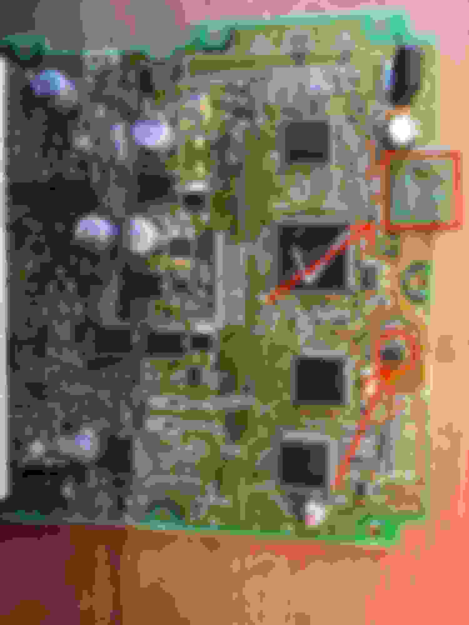
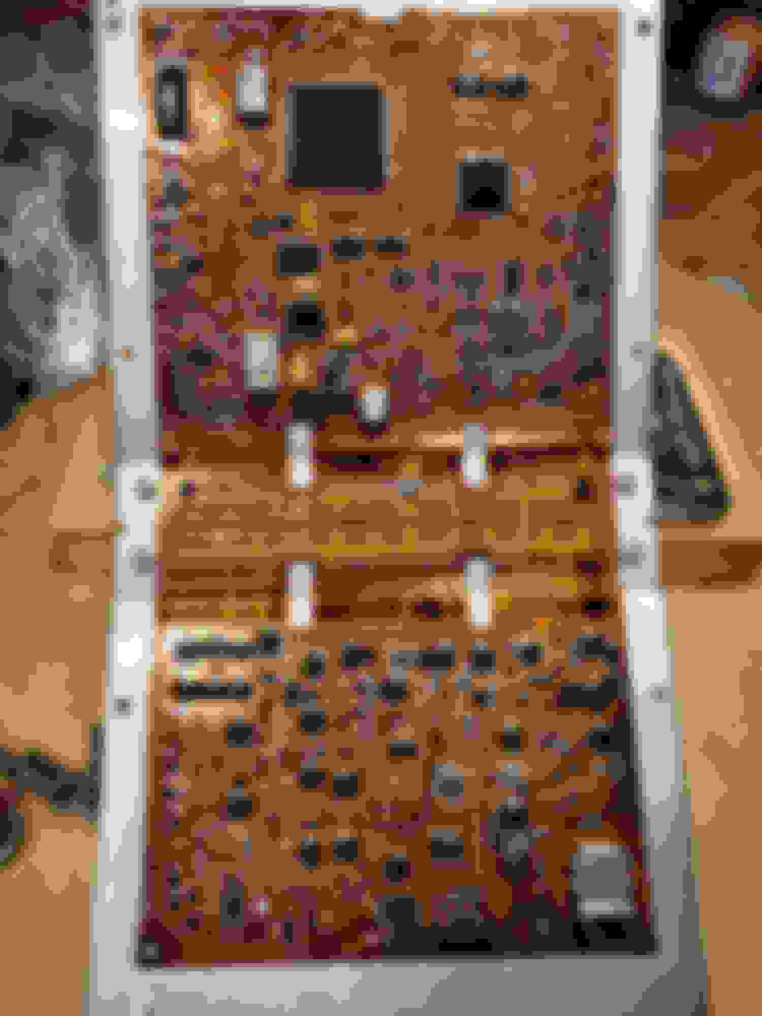
thought you guys might get a kick out of seeing the PCB that came out of my 05 Acura TSX's PCM. i commented already thanking you for the info and saying i was almost positive my car problem was due to the PCM but at that point i hadn't managed to get the PCM removed from the car (the bolts were REALLY stuck and took many tries & bolt loosening hacks before I finally managed to get it out.
now I'm stuck at a point where i can't get one of the screws out that holds the PCB inside the PCM shell. the corrosion weakened that screw to the point that it couldn't be unscrewed. every screwdriver i tried just continued to strip the screw!
do either of you (or anyone else) know what the square shaped IC is for? I've tried cleaning the top side of the PCB with alcohol but that one square chip is so messed up it's beyond hope! the immobilizer chip was also covered in corrosion but it's not quite as bad as the square one. hopefully it's still functional!!
there was a recall on the PCM/ECU in my car and it was taken to dealership where they supposedly performed the recall (put a plastic cover on the PCM but they didn't even put the cover on the right way. they should have removed the PCM (it's held in place with 2 bolts) and the cover has a cutout for one if the bolts to fit through.. like if it'd been installed correctly they would have had to remove the bolts then put the cover on and bolt it back, so the cover would be bolted in place as well. it wouldn't have mattered if they'd put it on tho bc I'm sure the PCM was already corroded...i mean the limp mode started just 5 weeks after taking the car in for recall & there's NO WAY that amount of corrosion accumulated in just a little over a month! the car stays in a garage 4 Christ sake! here you can see the square chip i was talking about better. notice the thick covering of red (rust?).. I've never seen corrosion that was so grainy like this?!
Re: DIY ECU/PCM Replacement (no honda re-flash required)
Wow, that's a lot of corrosion! Not sure if the immob EEPROM chip is good or not. Weird things can happen with random shorts in a PCB, and anything could have happened in this case. Most of those EEPROM chips are only rated for 5.5 volts, and voltage spikes much higher than that can kill them. Still, there's a good chance it still works, and I'd probably still try it. Although if the chip was bad, you'd be out the money for a used ECU that you couldn't use.
It looks like a lot of moisture got inside the ECU. I'm wondering if a coolant leak from the heater core might have caused this (I'm brainstorming for possible sources of liquid that could get to the ECU). The next question is whether the recall covered that, or if it was an unrelated issue like a bad electrical connector or something. If the recall covered a coolant leak, or whatever caused the corrosion, then I would insist the dealer make it right.
As to the square shaped chip, I have no idea. Electronically identical chips come in a variety of different physical packages, and I'm a very amateur level electronics person. I look for the number/letter code printed on the chip and google it; without numbers I'm down to random speculation, which is dependent on my understanding of the particular circuit I'm looking at. With something as complex as an ECU board, I'm totally lost without the chip code.
I'll be really interested to hear how this turns out for you. That's a really sucky situation, and I'm wishing you the best of luck!
Re: DIY ECU/PCM Replacement (no honda re-flash required)
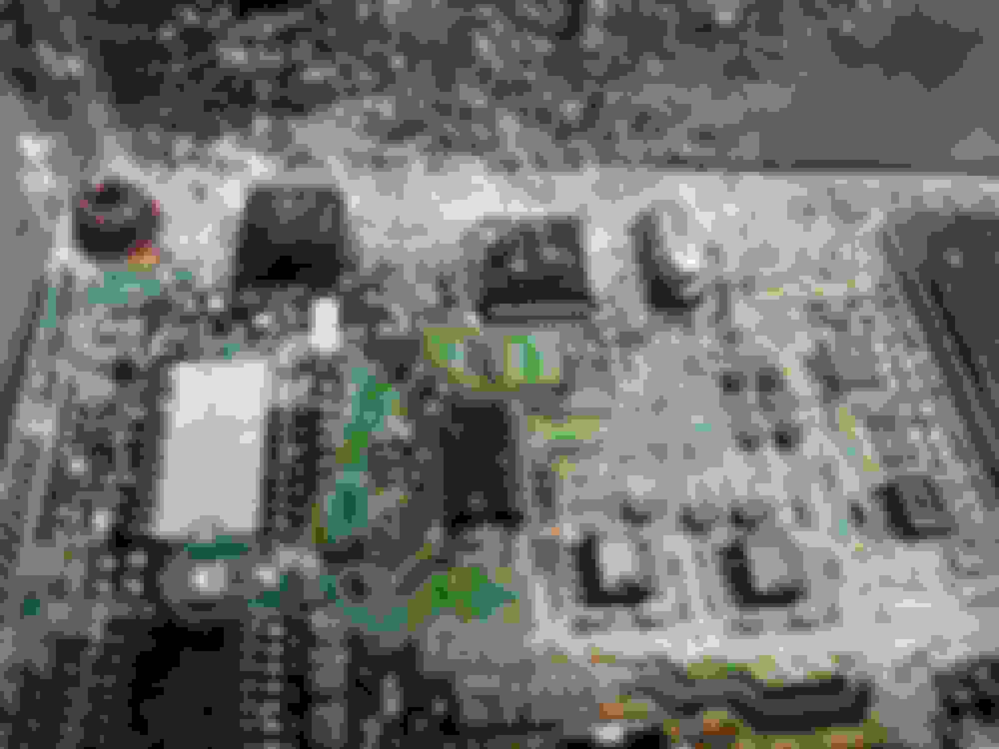
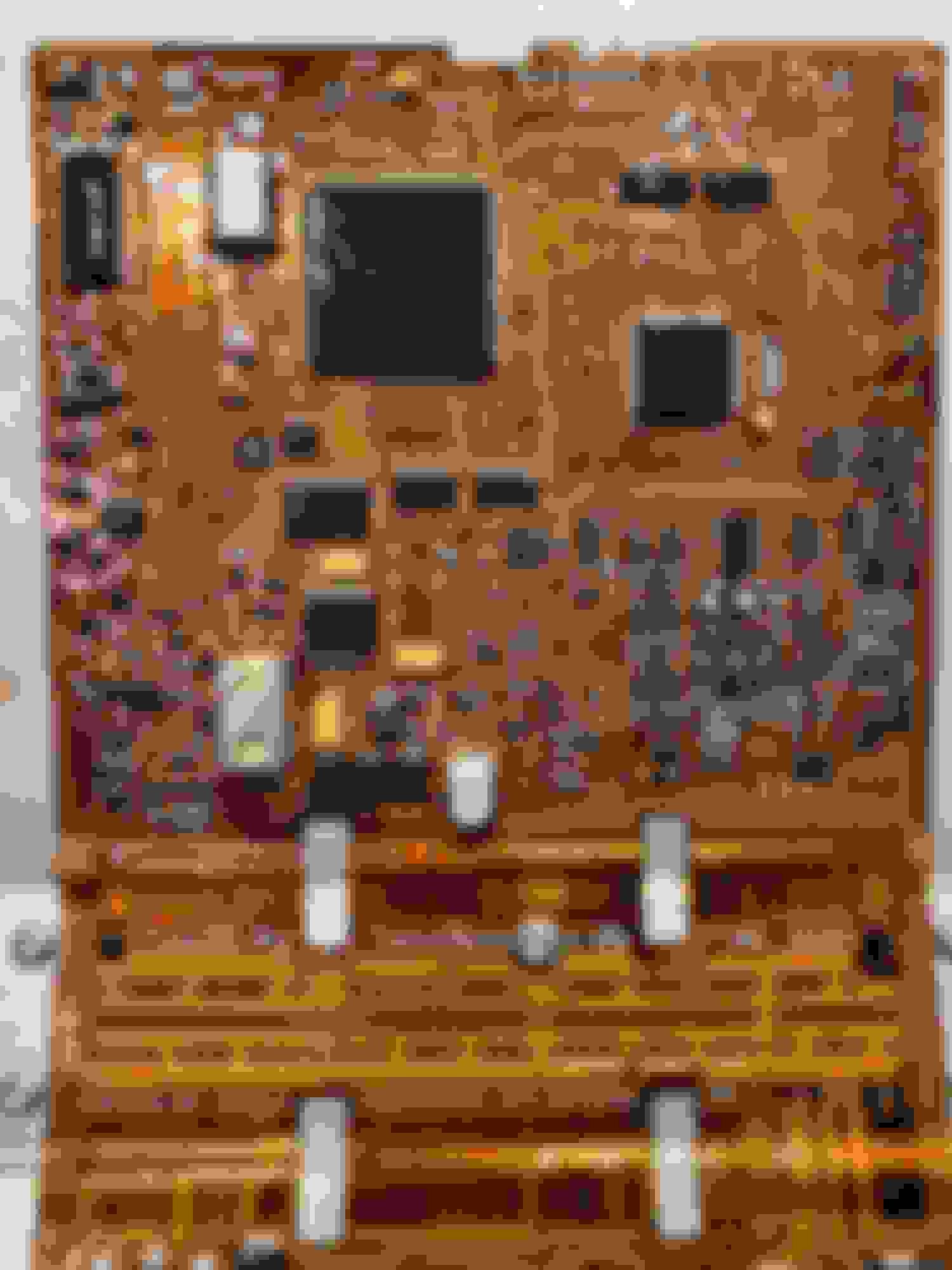
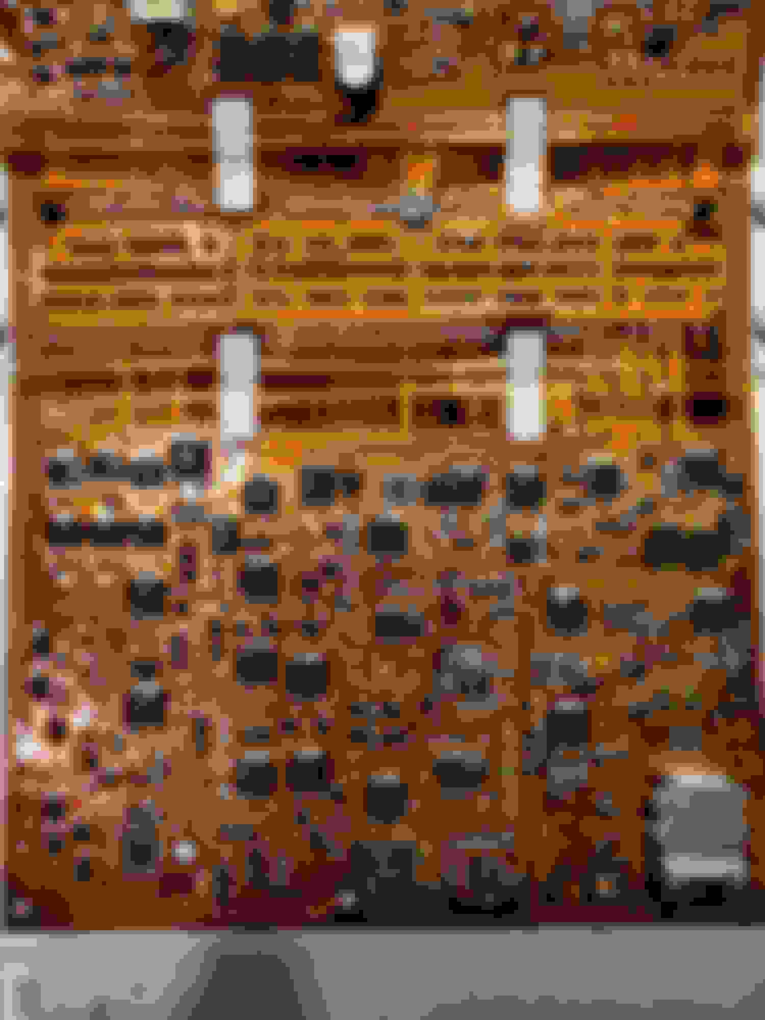
Man I've spent a rediculous amount of time trying to find info about that stupid 56 pin square chip. From what I've come to realize it must HAVE TO BE a proprietary chip..meaning there's no way to find a datasheet or a single thing about it actually. Here's a pic of what it looks like cleaned up where you can see the inscription. I'm thinking the 8 pin chip above it is the EEPROM but it doesn't have any imprint that I can see. If you can't tell from the pic the#26 pin is gone..completely disintegrated from corrosion! Pin 17 is lifted. The screws were so bad off in the corner with the most corrosion (which also happened to be the one with these chips) that I almost never got the screws out! Actually I didn't get the screw out of the housing..I just spun the lid around. The screw in that corner holding the PCB down had to be drilled out and torn to shreds to get the board out! Here's a shot showing a little more of the board and the whole chip that I believe to be the EEPROM. I accidently hit it when trying to get the screw out of that edge and its got a tiny little chip missing off the top..I'm thinking it's just the plastic and won't interfere with it's function but I could be wrong. I hope it's ok!!
As far as the recall..Well it's due to salt used to melt ice on roads..the floor board carpet touches the PCM and the solution can eventually work it's way into the ECU. That's def what happened with mine bc I took a pic and you can see corrosion on the carpet that was touching the PCM. The recall procedure only called for replacing the PCM if there was a certain DTC AND visible corrosion..if it just had corrosion they were told to clean the PCM off and apply the cover. It's obvious that the dealership did neither in my case however since there was so much corrosion on the PCM and the cover was just thrown in the hole where the PCM goes..not bolted down!
Here's the TSB for the recall procedure: and a pic of the PCM in the car Here you can see the edge of the carpet has corrosion on it! So yes the reason for the failure SHOULD be covered under recall but since the car didn't have that code technically they weren't even instructed to replace the PCM! This makes no sense to me because when electronics become corroded they can produce any number of outcomes..to only cover ONE outcome is rediculous!!
Im thinking of trying to take a similarly sized pin off of an old chip that's on a tv PCB I've got laying around and trying to solder it in where the missing pin is and resolder the lifted pin as well. I finally got some flux the other day and im going to test it out on some old PCB circuits before attempting anything on my cars circuit board. I'll let you know how things go and what I end up doing.
If I could get a ride to this pull your part place about an hr and 45 mins away I could get another PCM but nobody will take me as of yet. 😞
Re: DIY ECU/PCM Replacement (no honda re-flash required)
Though im an avid Honda owner and have worked on these cars for years i was dead stumped with this one. I made an account on this site to say THANK YOU GUYS! I'm not the best with electronics and only used a soldering iron like twice in my life. After reading all this information and watching a few videos on youtube i figured id give it a try. I used a low temp butane torch heated up the chip pulled it off and did the same to install it onto the other ecu which I actually already had laying around from a swap last year. At the end of the day as the OP said anything is possible if you put your mind to it. Thank you guys, i cant express that enough!
Re: DIY ECU/PCM Replacement (no honda re-flash required)
Originally Posted by miketunstall
Hey there Honda people,
I recently had to repair a 7th gen civic that had the alternator bolts break off when the engine was running causing the all too common issue of frying the ECU/PCM. When I had finished re installing the alternator the car was stuck in limp mode (stalling out, no power, PGM-FI relay clicking, no tach, and no com with ECU.
To fix this, grab yourself a used ECU. I went to my local U-Pull yard and got one for $40. Then remove the fried ECU and open it up. On the side of the board opposite the connectors there is a small EPROM chip labeled IC240. Remove this from the board and solder it in on in the new ECU. Next, de-solder the large green chip with 16 legs labeled HIC340 and solder it onto the new ECU. Now I'm not sure if that step is necessary (I thought this might have been part of the immobilizer) but it worked for me. Now just install the new ECU with the transferred parts into the car and it will be as good a new.
For only $40 and the time spent soldering, the car is back to normal and the best part is that you don't have to get towed to the stealership to have the car reprogrammed.
Did this but didnt change the green one in the ecu and have the green key light blinking now. Is this suppose to happen?? Any help would be great thanks!
Re: DIY ECU/PCM Replacement (no honda re-flash required)
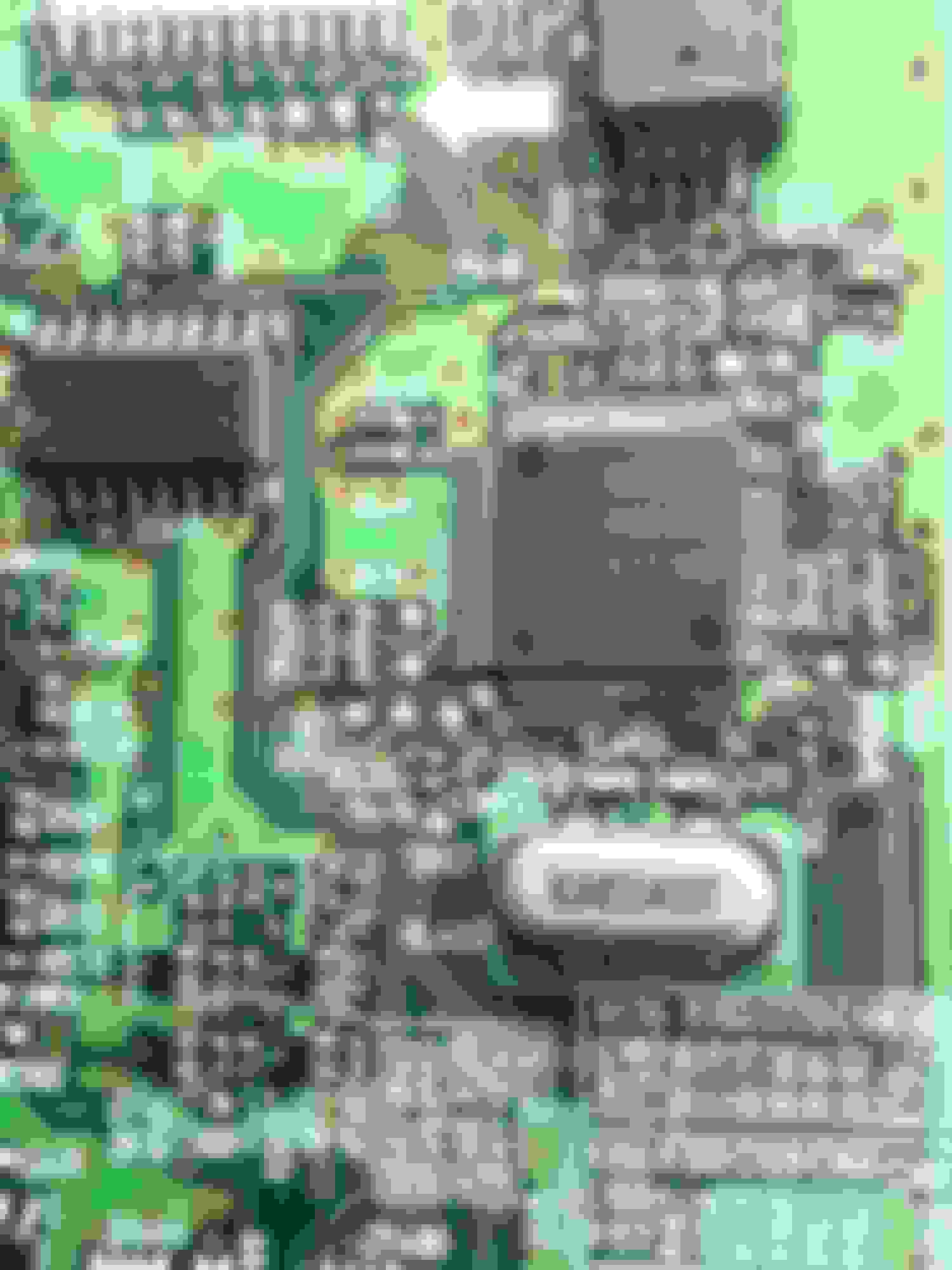
Folks, i have a 2000 Honda Accord that requires the swap shown below, however my circuit board looks very different. Any suggestions on how to identify the eeprom chip would be appreciated so i can implement the chip swap.
Re: DIY ECU/PCM Replacement (no honda re-flash required)
Your circuit board certainly looks different than mine. I was googling the subject of "2000 accord immob chip" and the chips I found tended to resemble the one shown at the 2:03 mark in this video
Looking at the photo of your ECU circuit board, I don't see anything resembling that; perhaps it's on the other side of the board, or maybe different models of Accords had different boards. Your board certainly looks different than the photos I've seen elsewhere. I'd keep googling, and in the meantime you could locate all the 8 pin chips that resemble the one I changed on mine, then google the numbers printed on the chips to see which ones are EEPROM chips. That would likely narrow things down to just a few potential chips, which you could change one at a time until you get the right one.
I also found this interesting immobilizer bypass trick for 97-01 Preludes. Not sure if your Accord works the same way, but if it does then it might give you a running car while you investigate this further.
Good luck figuring this out, and do post an update to enlighten the rest of us!
Re: DIY ECU/PCM Replacement (no honda re-flash required)
Jp88, thanks for the kind words, and I love that you were able to do this with a butane torch! I'm not online much, but this is a really cool forum and I love the collective knowledge and ingenuity possessed and shared among the people here. I share your appreciation for everyone's help!
Re: DIY ECU/PCM Replacement (no honda re-flash required)
Thanks for the quick reply John. Yes, for some reason, this board not only looks different, but it is also very difficult to find a similar images online that match Honda's found a couple, but they were Toyota. So the board is actually 'sandwiched' inside the ECM box, ie once you unscrew the sides, you then unfold the metal case to gain access to the full board! kinda weird actually. Anyhow, There are five 8 pin chips, two of three have identifiers on them, one of them is larger than the rest. I'm probably going to switch the larger chip and see what happens. .
Re: DIY ECU/PCM Replacement (no honda re-flash required)
Originally Posted by gilach
Folks, i have a 2000 Honda Accord that requires the swap shown below, however my circuit board looks very different. Any suggestions on how to identify the eeprom chip would be appreciated so i can implement the chip swap.
I have this exact same ECU (99 Honda Accord v6), by chance were you able to locate the immobilizer card chip ? I�ve been staring at this thing for hours and looking online and couldn�t not find any ecu similar to mine except for this one. Any guidance for locating this would be greatly appreciated
Re: DIY ECU/PCM Replacement (no honda re-flash required)
Hey guys,
By no means is what I'm about to describe the proper way to do this repair, but I was able to get my car to start and run without computer related issues by just removing the IC240 chip from the new board. I didn't need to transplant the immobilizer (IC240) chip to the new board to get the car to start and run. All gauges are working, and the car communicates with an OBD-II reader. The downside is that the green, immobilizer key light will still flash, and you very likely will have an engine code or two related to the fact that the immobilizer's missing. Read on for more details.
First of all, I have no experience working with circuit boards, soldering, etc. I understand the basic principles but have very little working ability or even knowledge. With that said, when I went to the junkyard, I decided to get two computers of similar model numbers that may work with my car: 37820-PLR-A12 and 37820-PLR-A13. (My car's original ECU was a 37820-PLR-A12.) Supposedly, these two are equivalent, and the A13 is just a "newer version". The first ECU I pulled was an A13; I decided I wanted an A12 just in case there was some difference and pulled one from another car. I brought both home from the junkyard. With both practice boards and the actual ECUs, I was having a lot of trouble getting chips off with just the iron and the desoldering wick. It looks like the hot air feature that jgavel mentioned back in 2019 really is necessary.
I started toying with the idea of sneaking something under the chips and prying them off. I did some on the practice boards, and the chips and boards seemed to be in decent shape after the procedure. Then, I took the tool to the A12 ECU from the junkyard and messily pried the IC240 chip off. The removal was so messy that I also removed two electrical components near the chip: the component with "ZEE" written on it in tiny letters to the left of the IC240 chip and the dark orange, unlabeled item with two silver ends above the IC240 chip. I then painstakingly superglued these items back on in what I believed to be the correct orientation, applying a little bit of down pressure on the items where possible while the glue dried so that maybe some of the electrical connectivity would remain.
At this point, I was certain I'd screwed up the board, but I figured I'd throw it in the car to find out just how badly. First, I checked the interior lights, which worked. Then, I checked the gauges: also working. I pressed down on the clutch and turned the key just for the hell of it. The car started in under half a second. The green key light on the dashed flashed, and the engine light was on, but I didn't really care. The car drove well.
My engine codes related to the ECU were...
P0607 (Control Module Performance): this code showed up immediately.
P0630 (VIN Not Programmed or Mismatch): this code took a few hours of playing with the car to present itself.
My engine codes unrelated to the ECU were...
P0135 (O2 Sensor Heater Circuit: Bank 1, Sensor 1)
P0141 (O2 Sensor Heater Circuit: Bank 1, Sensor 2)
When taking the car into the higher RPMs, I also triggered a P0340 (Camshaft Position Sensor) code at times. This put the car back into limp mode, where the RPM cannot exceed 3,400 RPM. I assume this is not related but am presently not completely sure. The car does run a little rough at times, and the idle often wanders, but I believe this is due to issues with the idle air control valve (IACV) and not due to issues with the computer itself.
Again, even though this isn't the proper way to do this, I wanted to share, and I thought I'd be good to have this listed here.
Re: DIY ECU/PCM Replacement (no honda re-flash required)
Originally Posted by nishanerd
I have this exact same ECU (99 Honda Accord v6), by chance were you able to locate the immobilizer card chip ? I�ve been staring at this thing for hours and looking online and couldn�t not find any ecu similar to mine except for this one. Any guidance for locating this would be greatly appreciated
Unfortunately there's not a big knowledge base for the Motorola ecus that came in the V6 cars, like there is for the Keihin/IPT ecus that came in virtually everything else back then. Probably just going to have to suck it up and find a dealer that can get you going.
Re: DIY ECU/PCM Replacement (no honda re-flash required)
Originally Posted by miketunstall
Hey there Honda people,
I recently had to repair a 7th gen civic that had the alternator bolts break off when the engine was running causing the all too common issue of frying the ECU/PCM. When I had finished re installing the alternator the car was stuck in limp mode (stalling out, no power, PGM-FI relay clicking, no tach, and no com with ECU.
To fix this, grab yourself a used ECU. I went to my local U-Pull yard and got one for $40. Then remove the fried ECU and open it up. On the side of the board opposite the connectors there is a small EPROM chip labeled IC240. Remove this from the board and solder it in on in the new ECU. Next, de-solder the large green chip with 16 legs labeled HIC340 and solder it onto the new ECU. Now I'm not sure if that step is necessary (I thought this might have been part of the immobilizer) but it worked for me. Now just install the new ECU with the transferred parts into the car and it will be as good a new.
For only $40 and the time spent soldering, the car is back to normal and the best part is that you don't have to get towed to the stealership to have the car reprogrammed.
planing to swap the ecu from a non vtec to vtec will the chip need additional programing or are the chips only related to the keys?

 04-03-2017, 10:23 AM