
Experienced Engine Builder/Designer help request: Formulas and Part selections.
 06-23-2015, 04:08 PM
#76
Honda-Tech Member
An interesting read... but It looks like they tested a 2 valve per cylinder engine and the pistons appear to be from a diesel.
Idk if you can accurately compare those results to a higher revving gasoline 4 valve Honda engine...
Something you might find interesting is the old Honda cvcc engine. I forgot exactly what they did but it had something to do with piston design and/or valve opening to promote swirl inside the combustion chamber. Another interesting read is the roller wave theory by Endyn.
 06-23-2015, 05:30 PM
#77
Hysterically Calm
Thread Starter
Something you might find interesting is the old Honda cvcc engine. I forgot exactly what they did but it had something to do with piston design and/or valve opening to promote swirl inside the combustion chamber. Another interesting read is the roller wave theory by Endyn.
I will see what I come across with Roller Wave Theory.
As for the 2 valve motor and 4 valve, I think the results still will have some influence. The paper seems to be leening more towards the tumble aspect.
Now I can't say I fully comprehend tumble and swirl being considered as parallel and perpendicular to the piston axis (y axis?). However seeing the flow vectoring/amplitudes between the symetrical piston to the asymetrical sort of makes sense, the offset depression causes a funky low pressure spot that the flow is attracted to causing more turbulence.
Of course this is assuming the intensity of color between the two graphs is proportional to flow amplitudes and that I'm comprehending the diagrams correctly.
Thanks for the Endyn hint, and I'll need to revisit the CVCC technology. I believe that's where lean burn was figured out by Honda which was later utilized again in their VX/HX and 3 stage D15B motors long after the 70's CVCC civics had left the scene.
Also got to read the first 5 pages of this SAE paper under preview mode, have to pay $25 dollars for the remaining 12 pages.
http://papers.sae.org/2013-01-2797/
The first 5 pages shows a 5-13% increase in air velocity with the dish piston compared to flat top. And yet, I've seen some builders say they always see more power with higher compression which usually means domed pistons....... Go figure.
Last edited by TomCat39; 06-23-2015 at 06:59 PM.
06-25-2015, 05:28 PM
#78
Hysterically Calm
Thread Starter
Something you might find interesting is the old Honda cvcc engine. I forgot exactly what they did but it had something to do with piston design and/or valve opening to promote swirl inside the combustion chamber. Another interesting read is the roller wave theory by Endyn.
I had actually already read one of T.O.O. archived articles on quench which just baffled the snot out of me at the time as I had no idea what anything was.
Anyways, the last couple of days I've been reading and trying to soak in all the critical articles at EnDyn as it's all relevant and they really seem to have figured out a great many things LONG before anyone else and raising the bar for everyone.
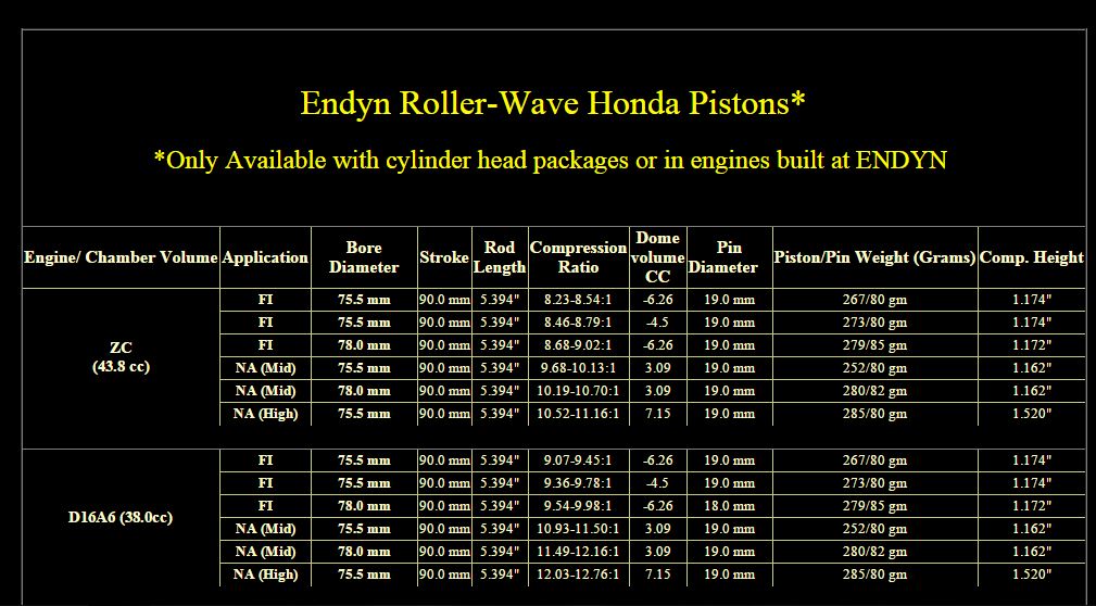
Of note, to go with that Roller Wave Pistons (only available with a Head Package) information there is the "Soft Head" article. If you notice a trend including with the original article I posted with the offset piston, asymmetrical crown design plays a HUGE roll in improving things.
http://www.theoldone.com/articles/The_Soft_Head_1999/
I might not be able to get the Roller Wave Pistons as I don't want to invest heavily into a D series build (700 for the basic head package not counting parts) but I might be able to use some of the concepts to modify the PMS pistons some.
I've noticed that even the Roller Wave Pistons put a lip on the intake side to help create a soft head as well as asymmetrical valve relief designs with a couple of cool things on the intake. I might not be able to add the shallow gouge/fence on the back side of the intake reliefs but it might be possible to make the tongue part and do a valve trough on the exhaust side. Also shave off a portion of the exhaust side of the dome.
These tricks mimic some of what EnDyn has formulated and it just might prove highly fruitful and I think it should be pretty straight forward for a machine shop to CNC on new PMS pistons.
One thought that occurs to me though, with asymmetrical designs, is the skirt weighted differently to balance out the piston? Just how balanced are pistons? I mean even stock PMS pistons have a difference in the crown, only one side has valve reliefs. Is the weight taken off else where on the other side of the piston?
06-25-2015, 06:00 PM
#79
Honda-Tech Member
I believe they will sell you pistons by themselves. I purchased a set From them a few years back no questions asked.
Mine have symmetrical skirts. They're not full skirts but they are the same on both sides.
I think I saw some pistons not too long ago with asymmetric skirts. I think it was wiseco also but don't remember the application.
Yes a lot of what Endyn says and does I have verified with what other hot rodders and v8 guys have been doing for some time. Even some similarities in theories between all types of racing as well as what some high end OEM manufacturers implement in production cars. All having to do with improved mixing of the AF mixture and trying to concentrate the combustion at specific parts in the cylinder.
06-25-2015, 07:19 PM
#80
Hysterically Calm
Thread Starter
JE Releases Asymmetrical Piston Designs! - JE Pistons
Google shows Wiseco with some too by the looks.
I'm more wondering about weight balance based on the fulcrum point of the wrist pin. Is the piston balanced on each side of the wrist pin even when valve reliefs are different?
06-25-2015, 07:33 PM
#81
Honda-Tech Member
According to your link to JE pistons, the wristpin has been moved slightly to the major thrust side to keep the piston "nearly perfect".
They also claim to clear the oil squirters with their new design (something I consider pretty important and should be retained if at all possible)
They also claim to clear the oil squirters with their new design (something I consider pretty important and should be retained if at all possible)
 06-30-2015, 06:25 PM
#83
Anti-GDD White Knight Simp
Been away for a while, just catching up. Going back to rod length for a moment:
I do not believe that "power and rod length are on opposite sides of the same stick."
Rather, power is on both ends of the stick, it is just achieved in different ways. On one end of the spectrum, there is the "American" way- increase stroke thus increasing displacement (very torque-y).
On the other end of the spectrum, however, we may find power also, by looking to Formula One (people laughed at me when I first came on this forum making comparisons to the pinnacle of motorsports, but the fact is it can be done in any performance application). On this opposing side to the "American" way, we find extremely short strokes with very large cylinder bores. In contrast to increasing stroke, a smaller stroke will tend to produce higer horsepower at much higher RPMs, but without the low-end torque of a stroked motor.
In summary,
Long Stroke:
Pros- easy to achieve great torque and horsepower. Increase in displacement multiplies the effects of forced induction. Because it does not require very high RPM to produce power, it is generally suitable for street use.
Cons- Sharper rod angles create more work performed by the engine, and create more wear. RPM is greatly limited.
Short Stroke/ Large Bore:
Pros- Longer rod length, less severe rod angles, less work and wear on the motor. Utilizes the best of both worlds, high displacement and high RPM (Torque and HP are a function of both).
Cons- Generally not suitable for street use since power is not made until high RPMs. Very high RPMs cause increased friction and heat, special care must be taken for assembly and lubrication.
If there is a replacement for displacement, it's high RPM.
07-01-2015, 10:43 AM
#84
Hysterically Calm
Thread Starter
Long Stroke:
Pros- easy to achieve great torque and horsepower. Increase in displacement multiplies the effects of forced induction. Because it does not require very high RPM to produce power, it is generally suitable for street use.
Cons- Sharper rod angles create more work performed by the engine, and create more wear. RPM is greatly limited.
Short Stroke/ Large Bore:
Pros- Longer rod length, less severe rod angles, less work and wear on the motor. Utilizes the best of both worlds, high displacement and high RPM (Torque and HP are a function of both).
Cons- Generally not suitable for street use since power is not made until high RPMs. Very high RPMs cause increased friction and heat, special care must be taken for assembly and lubrication.
If there is a replacement for displacement, it's high RPM.
The other question I have is do you finally get torque with the higher RPM? I mean really horsepower isn't anything really, it's more about torque as it's the torque that pushes the car.... I mean it's my understanding that a lower HP car with higher torque can out perform a higher HP car with less torque.
07-01-2015, 07:27 PM
#85
Anti-GDD White Knight Simp
Thinking about this, ideally if you could rev the stroker motor (short rod/long stroke) to the same levels it would be superior. But because of the sharper angles and higher engine wear, I'm assuming there is a limit to the RPM and that's where the longer rod combo excels due to the smaller angles and reduced engine wear?
The other question I have is do you finally get torque with the higher RPM? I mean really horsepower isn't anything really, it's more about torque as it's the torque that pushes the car.... I mean it's my understanding that a lower HP car with higher torque can out perform a higher HP car with less torque.
The other question I have is do you finally get torque with the higher RPM? I mean really horsepower isn't anything really, it's more about torque as it's the torque that pushes the car.... I mean it's my understanding that a lower HP car with higher torque can out perform a higher HP car with less torque.
To your second question: It all depends on how a particular engine is built. Think of all of the different variables and part selection that can move the torque curve up or down in the RPM range, or make you gain the most torque in a certain area of that range. For internals, camshaft, headwork, piston, and crank/rod selection obviously are going to be selected to achieve a goal, whether it be a low RPM grinder or high RPM screamer. Looking past the internals, the dimensions of the intake system and exhaust headers can drastically change where power is made in the RPM range, thus allowing further fine tuning of the system.
Now, let's look at the most common formula for horsepower calculation:
HP=(RPM * T) / 5252
5252 is always constant, so the only changing variables are RPM and Torque. Stroker motors make a lot of horsepower because torque is higher with a longer stroke, even though there isn't a lot of RPM in the equation.
Conversely, high RPM engines make their power from high RPM, even though the torque will not match that of a stroker.
It should now go without saying, that to build an engine with the highest potential for power, it needs both high RPM and to make the most torque at that high RPM.
07-07-2015, 09:48 PM
#86
Hysterically Calm
Thread Starter
I redid all my measurements on the Z6 IM. So I don't loose them I shall put them here.
First off, runner area is 961.23 mm�. Radius of half the circle part is 11.5 mm. Total width of the ID of the runner is 41.5 mm and the height is 29.5 mm.
Once you subtract the diameter from the width you get the width of the square/retangler portion of the intake which is 29.5x18.5 mm which equals 545.75 mm�. Then the area of the circular potion is pi*r� which equals 415.4756 mm�. Add them up and you get your grand total of 961.2256 mm�.
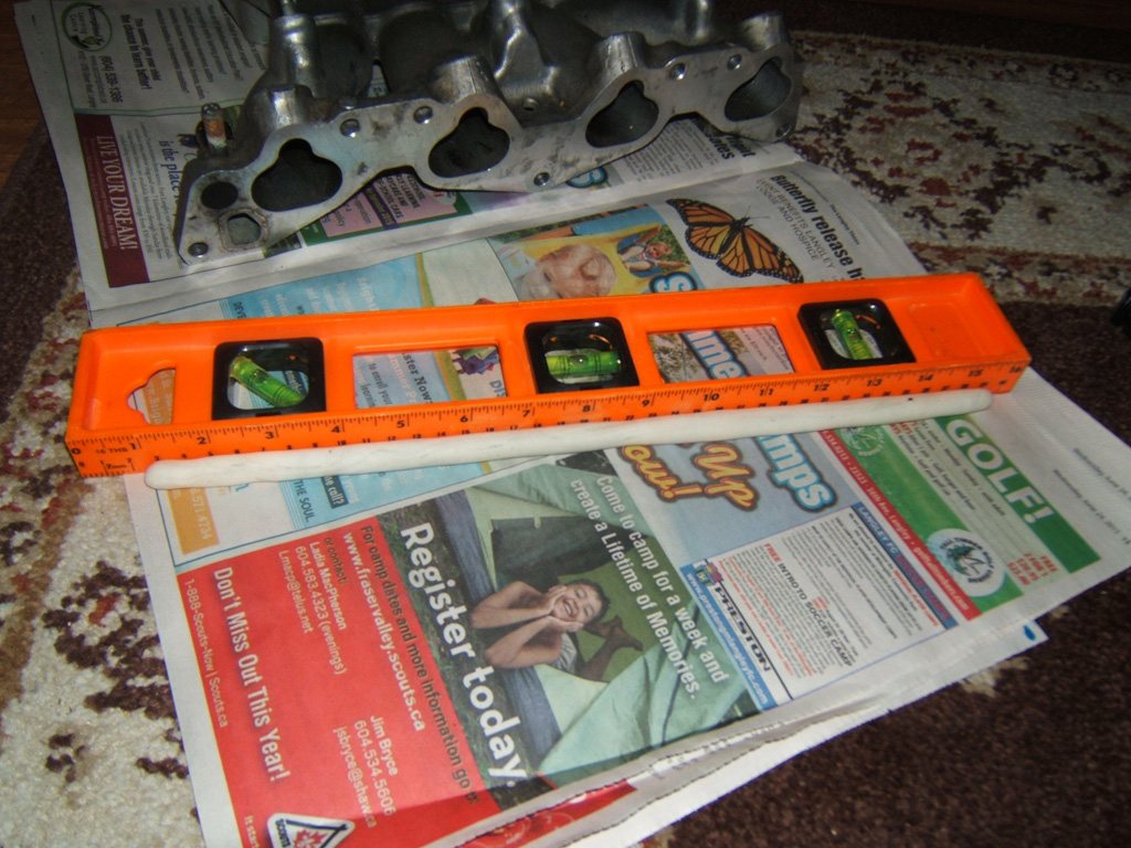
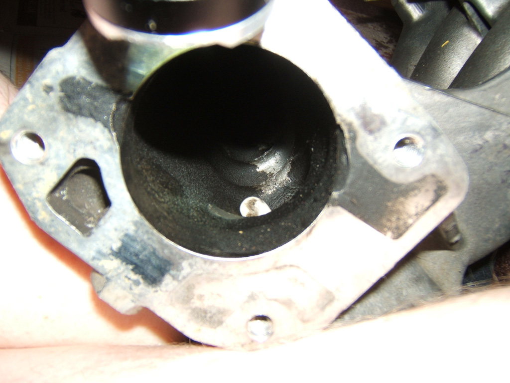
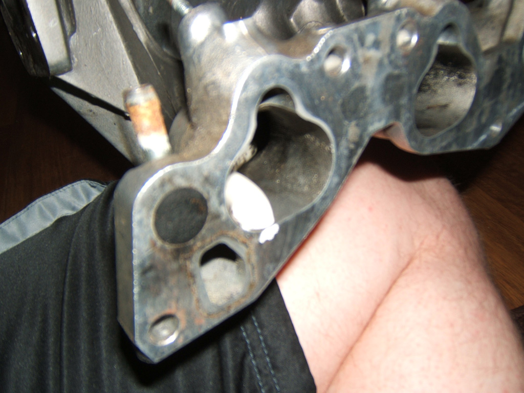
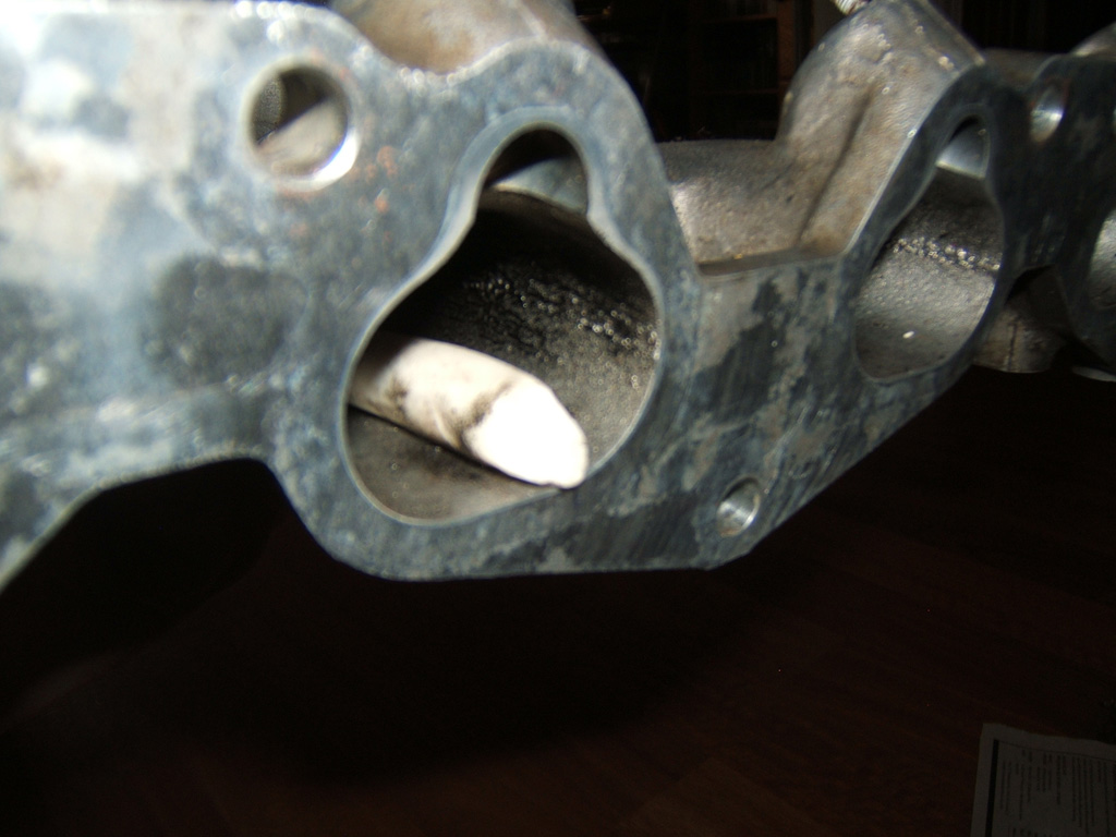
The following pictures show how I measured runner length. Information I found on the internet said the runners are 12" long. With clay I found them to be 11.41" or 29cm. As can be see the clay went equal to the lowest portion of the horn. I measured both runner #4 and #3 and they were the same.
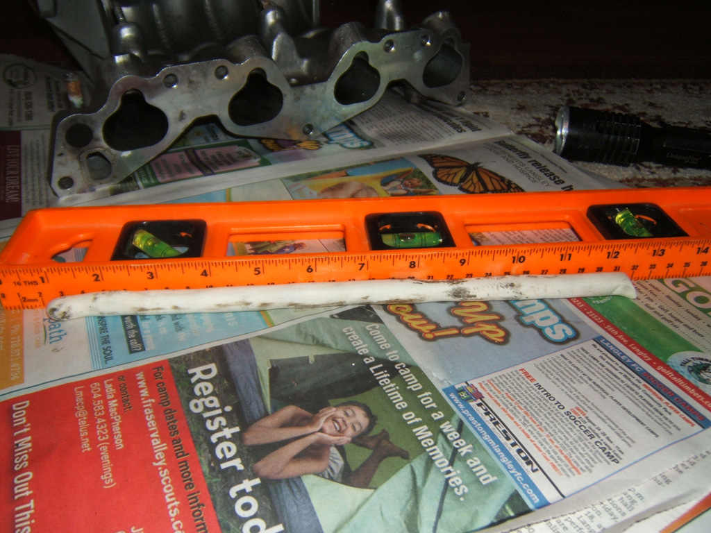
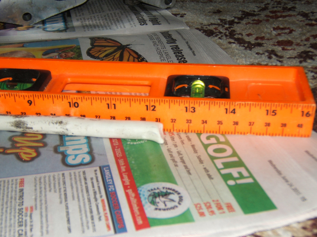
The first photo shows where I made the clay over 13 inches so there was some extra over the runner. The next 4 shots shows the clay in position in both runners on both ends, and the last shots show the measurement clay roll.
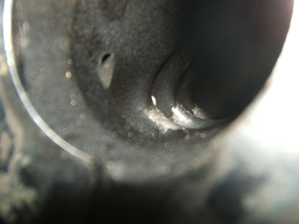
I measured the distance from the edge of the Y8 head to the bottom of the valve seat/top of the combustion chamber and it was about 3.5 inches.
Converting that over it's about 9 cm. I did it awhile ago so I might just redo it and measure it in CM. Seems to work out better than in inches.
So anyways, that means a total runner length of just shy of 15 inches to the bottom of the valve for a D16Z6 IM with a runner area of 961.23 mm� which is 9.6123 cm�.
First off, runner area is 961.23 mm�. Radius of half the circle part is 11.5 mm. Total width of the ID of the runner is 41.5 mm and the height is 29.5 mm.
Once you subtract the diameter from the width you get the width of the square/retangler portion of the intake which is 29.5x18.5 mm which equals 545.75 mm�. Then the area of the circular potion is pi*r� which equals 415.4756 mm�. Add them up and you get your grand total of 961.2256 mm�.
The following pictures show how I measured runner length. Information I found on the internet said the runners are 12" long. With clay I found them to be 11.41" or 29cm. As can be see the clay went equal to the lowest portion of the horn. I measured both runner #4 and #3 and they were the same.
The first photo shows where I made the clay over 13 inches so there was some extra over the runner. The next 4 shots shows the clay in position in both runners on both ends, and the last shots show the measurement clay roll.
I measured the distance from the edge of the Y8 head to the bottom of the valve seat/top of the combustion chamber and it was about 3.5 inches.
Converting that over it's about 9 cm. I did it awhile ago so I might just redo it and measure it in CM. Seems to work out better than in inches.
So anyways, that means a total runner length of just shy of 15 inches to the bottom of the valve for a D16Z6 IM with a runner area of 961.23 mm� which is 9.6123 cm�.
Last edited by TomCat39; 08-30-2015 at 05:31 PM. Reason: Optimized Pics
08-26-2015, 04:06 PM
#87
Anti-GDD White Knight Simp
What ever happened to this thread? Are you still figuring out calculations or did "life happen"?
Question: When we are calculating runner length (as for a custom induction system) do we include the length from the edge of the head to the bottom of the valve? I hadn't even thought of that to be honest
Question: When we are calculating runner length (as for a custom induction system) do we include the length from the edge of the head to the bottom of the valve? I hadn't even thought of that to be honest
08-26-2015, 05:19 PM
#88
Hysterically Calm
Thread Starter
Yeah more or less, life has happened as well as finding quality easy to use formulas without spending thousands of dollars on college for engineering.....
I need to optimize the pics I put in this thread and will be getting back to it.
Work has overloaded me so I haven't been doing much of any of my hobby car stuffs for awhile.
I'm also in the middle of blue printing my block.
As for your question, from everything I've seen as I have understood it, you count the runner and the head portion to the bottom of the valve as part of your runner calculations, not just the runner itself.
So the Z6 runner on the Y8 head is more like 16 inches not the 12 of the runner itself.
Don't worry, once my family has returned home in a few weeks, I still have the Y8 IM to measure. And then I can revisit the Runner calculations and Runner Area calculations.
I think the area that will be most challenging is the plenum "resonance" as the resources for the formulas seems to be defunct at Team Integra and I trust their write ups over that FTL racing quite significantly.
08-26-2015, 07:15 PM
#89
Anti-GDD White Knight Simp
Just to simplify where this thread is going next, can you state what formulas you need exactly? When you have time of course. I know what you need is stated somewhere previously, but it's jumbled somewhere in the discussion of the strenths and weaknesses of the FTL formulas 
I just finished researching a bunch about intake runner calculations for ram tuning, and all here on H-T believe it or not. So far, the best formula I've found is in a thread that is linked in the "similar threads" box at the bottom of this page. It's called "calculating intake runner length get out your vtak calculator Yo!", by Rosko. I think you may be very interested in that.
I pray your family has a safe return, wherever they are
And what exactly do you mean that the "plenum 'resonance'" will be a challenge? Perhaps the Rosko thread will provide an answer
08-27-2015, 09:17 AM
#90
Hysterically Calm
Thread Starter
Awesome stuff, I will go looking for that thread.
As for plenum resonance, the formula was a pic that is broken on Team Integra and I believe it displayed the Helmholtz formula used for plenum resonance so you knew at what rpm you would get the extra "ram" push from the resonance.
And yeah, I agree fully this thread has really become a miss-mash sort of like an initial draft. Was wondering if I should just edit my first few posts and quote the original posts for historic purposes or create a new thread with just the relevant formulas and demonstrations of once it's all deciphered.
Not really sure, even though I am leaning towards a new cleaner thread.
Here is the thread you mentioned, putting it here for safe keeping:
https://honda-tech.com/honda-prelude...or-yo-1963201/
08-27-2015, 04:37 PM
#91
Anti-GDD White Knight Simp
Oh ok, well as for the "plenum resonance" equation, that is found in the Rosko thread I believe. The acoustic "supercharging" is almost entirely dependant on runner length it seems, and the best, most specific equation I've been able to find is in that thread. The math even makes sense, and this coming from a guy who isn't very strong in math.
Now I may need to provide clarity here, on something that Rosko and others were unsure about in that thread:
The equation does work for both ITBs and regular plenum manifolds, however it does this in different ways. In a plenum manifold, the reflected wave meets the high pressure charged zone of the plenum, and a positive reflection wave is sent back to the valve. With an open ITB runner, the reflected wave reaches the bellmouth and escapes into the atmosphere. However, this in turn sends a negative pressure wave back towards the valve, the strength of which is proportional to the difference in pressure between the pressure inside the runner to the atmospheric pressure.
One thing I would like to find is how to find the proper plenum size for optimal positive pressure waves. It may help you in your D series manifold quest, and would help me in a design I'm undertaking. I will research tonight
08-30-2015, 01:34 PM
#92
Hysterically Calm
Thread Starter
Yeah, that's where I was struggling to find any really solid information as Team Integra has the broken picture for that one aspect.
Also after reading this thread, and this thread, I found that there is a model based on acoustic impedance. It's 25 dollars and definitely might be a good purchase for intake design.
Development and Validation of an Impedance Transform Model for High Speed Engines
None the less, after the two mentioned threads that pointed me at the SAE paper, I noticed everyone pretty much says the same thing. The math can take you about 80% there, then you still need to prototype and test. So really, unless you have serious cash for dyno tuning multiple times.... We can only get so close even with all the math in hand.
I think I was a bit discouraged as that was pretty much the consensus I had before, coupled with not being able to find any clear information on the Helmholtz applied to the Intake Manifold for Plenum being available..... I decided to take a break.
The Impedance Model seems to be a bit more useful and just may take us closer regardless of design.
The math seems to be abundantly available for runner length and runner area.... It's the plenum that I've only seen estimations of "Plenum should be 50-60% of engine displacement" and no math to say why or whatnot.
With that being said, I really wasn't too sure how to proceed. At least this round of research I came up with another viable model that has been verified and in the preview of the first 3 pages, the paper is just plum full of math to use for any intake design.
And then I just found this thread which has a couple fo really good tidbits as far as I can tell and it seems the best method to isolate plenum size is by determining the volumetric efficiency of the motor and working from that:
http://www.eng-tips.com/viewthread.cfm?qid=81167
08-30-2015, 05:23 PM
#93
Anti-GDD White Knight Simp
Thanks for the links, I will have to read them when I have more time. As for plenum design, I found out a little more than the 50-60% rule, but not much. For plenum design, the consensus is that you just have to test out different configurations and sizes to find out what works.
I have an H series, so I have the privilege simply bolting in spacers to increase plenum volume, as well as using custom plenum shapes. Soon (once I'm practiced up) I will be making a custom sheet metal plenum design or two, and will dyno test different combinations of plenum shape and volume, Lord willing. Hopefully I may be able to find some valuable information concerning their design
I have an H series, so I have the privilege simply bolting in spacers to increase plenum volume, as well as using custom plenum shapes. Soon (once I'm practiced up) I will be making a custom sheet metal plenum design or two, and will dyno test different combinations of plenum shape and volume, Lord willing. Hopefully I may be able to find some valuable information concerning their design
12-14-2015, 09:45 AM
#94
Hysterically Calm
Thread Starter
Revisiting this messy thread and thinking about branching it up into different aspects of it and keeping this as the draft mess thread.
There have been some really good nuggets of information provided by members here including this post I'm quoting. I don't think I understood or responded well to many of them and for that I apologize.
Thank you, I can't say I follow you but I'm sure I may in time.
I totally get this and understand that is the method 99.9% of the time. The goals you speak of I understand to be the desired end results. In this one off case, I am not overly concerned with the end results per say except knowing what they are once I reach the end. Then I can compare the end results with the choices made based on a few foundational decisions. I hope that makes sense.
Yeah I get this. I think the goal here was to find an event to be able to make the calculations with the formulas found. However, your point is very important to understand, which I didn't at the time. Now after pumping through the information a few times I understand what you were saying. I thank you for attempting to raise my awareness and apologize that I just didn't get it.
That last statement I am sure applies to many people who have replied in this thread. For all of you.... Thank You, Sincerely.

There have been some really good nuggets of information provided by members here including this post I'm quoting. I don't think I understood or responded well to many of them and for that I apologize.
trying to figure the lsa and everything on a single cam is pointless, since you cannot do anything to change it, youre pretty much stuck with manufacture specs. one of the beauties of running a single cam is you never have to worry about lsa and v2v....ever, if the cams designed right/
That last statement I am sure applies to many people who have replied in this thread. For all of you.... Thank You, Sincerely.
12-17-2015, 12:27 PM
#95
Honda-Tech Member
Join Date: Jan 2008
Posts: 755
Likes: 0
Received 0 Likes
on
0 Posts
I redid all my measurements on the Z6 IM. So I don't loose them I shall put them here.
First off, runner area is 961.23 mm�. Radius of half the circle part is 11.5 mm. Total width of the ID of the runner is 41.5 mm and the height is 29.5 mm.
Once you subtract the diameter from the width you get the width of the square/retangler portion of the intake which is 29.5x18.5 mm which equals 545.75 mm�. Then the area of the circular potion is pi*r� which equals 415.4756 mm�. Add them up and you get your grand total of 961.2256 mm�.
The following pictures show how I measured runner length. Information I found on the internet said the runners are 12" long. With clay I found them to be 11.41" or 29cm. As can be see the clay went equal to the lowest portion of the horn. I measured both runner #4 and #3 and they were the same.
The first photo shows where I made the clay over 13 inches so there was some extra over the runner. The next 4 shots shows the clay in position in both runners on both ends, and the last shots show the measurement clay roll.
I measured the distance from the edge of the Y8 head to the bottom of the valve seat/top of the combustion chamber and it was about 3.5 inches.
Converting that over it's about 9 cm. I did it awhile ago so I might just redo it and measure it in CM. Seems to work out better than in inches.
So anyways, that means a total runner length of just shy of 15 inches to the bottom of the valve for a D16Z6 IM with a runner area of 961.23 mm� which is 9.6123 cm�.
12-22-2015, 09:47 AM
#96
Hysterically Calm
Thread Starter
Sorta, one of the theories has to do with runner length as well as I think the runner size.
Also, doesn't water fill the injector pocket? I would think you would want to sort of ignore that pocket as I think ideally there would just be a straight tube runner to the valves etc.
I'll have to revisit the formulas to re-familiarize myself with it all before too long. I was pretty sure there was more required than just volume but could be mistaken.
12-22-2015, 11:56 AM
#97
Honda-Tech Member
Join Date: Jan 2008
Posts: 755
Likes: 0
Received 0 Likes
on
0 Posts
tomcat, You can use the clay to fill in those areas if you want. Runner length is a little easier to calculate, you can measure short turn radius and long turn radius. Add and divide to get your avg.
12-24-2015, 07:34 AM
#99
Hysterically Calm
Thread Starter
That's why for runner length I used a roll of clay stuck it in and got the tip even with the top of the horn of the runner, and cut the bottom edge off, slid out the clay and measured my roll.
I had thought about the longer and shorter radius but dismissed it. From what you just stated, I believe that was a mistake.
I will have to rework the intakes (got 3 to look at), thanks. And great tip of filling the unwanted areas with clay. That's awesome stuff.
12-24-2015, 03:40 PM
#100
Anti-GDD White Knight Simp
Yes, any "horn" is part of runner length. One reason why using different "v-stacks" can have big effects.
I can't quite envision how intake runner horns would pose a problem when using the "water method"
I can't quite envision how intake runner horns would pose a problem when using the "water method"