

Experienced Engine Builder/Designer help request: Formulas and Part selections.

Thread Starter
Hysterically Calm


Joined: Jan 2013
Posts: 10,439
Likes: 597
Hi all,
I've been studying and learning the complexities of part selection in the engine build process.
Reading through this well detailed thread by Michael Delaney at team integra has been helpful however, one of the formulas was in a pic for plenum resonance and the pic is broken. When I google the Helmholtz Resonator Calculations I don't get the formula specifically for engine/intake manifold that is referenced in the post.
The other challenge is that many of the intakes don't have full specifications available such as runner area, so without parts in hand it's challenging to get the number to crunch.
The parts set in stone (as I already have most of them) are the D15B7 block (1493cc displacement), D15B7 crank (Stroke 84.5mm), Z6 rods (137mm), 01-03 GX PMS-A00 pistons (27mm ComHeight), D16Y8 head (11.62 CR ratio Static/Effective) with the Felpro 9915PT HG. I've been told the compressed thickness of that felpro is 0.027" which seems pretty probable as I had to retard my stock B7 by a .5*-.75* ignition timing to stop pinging after the head gasket change due to the bump in CR.
The parts left to decide on is cam shaft, intake manifold and throttle body.
Using this calculator: Inlet Runner and Peak Torque Calculator
I roughly figured out the runner area of the Y8 intake manifold to have a peak torque at around 7200-7500 rpm based on the Y8 intake port size measurements.
I don't have all the measurement avaliable for the Z6 IM, and haven't looked solidly at the Skunk2 manifold and the Edlebrock Performer X is marked race only so am concerned it's not "street legal" for a daily driver.
Then I read this paragraph to just add to the complexities of it all:
So now with that, I realize, I'm in over my head and need some experienced help on choosing the last of the engine parts of this build.
The car is to be a daily driver, not a track car and I might get involved with a introductory or less serious autocross group but nothing really serious like some of the groups get.
With that, I am not sure where you would want peak torque to land if we are to set a rev limit of 7800.
I chose 7800 based off of the longer rods, vtec and also looking at the Crower 63441Y Stage 1 cam for the Y8 head.
Or leaving the cam stock.
At this point, I've been reading pages upon pages of information and formulas and I haven't been lucky enough to find any one resource that can provide guidance to decipher the last 3 pieces of the motor (cam, intake manifold, throttle body) for a daily driver with a bump to the fun attitude side with the least sacrifice of the lower and midrange Honda designed into these grocery getter motors.
Is there any experienced engine designers/builders who would be willing to baby step me through the last of the process? I'm not in a huge hurry as this is the planning stages, I really don't want to go the trial and error route. I'd rather learn how to do the math step by step to have a fair idea of what each part will do to the system.
Please if anyone can provide guidance, I'll be very grateful. I'm not even sure where to start for these last 3 pieces for an NA motor.
Sorry for the long post, it's just so friggin complex (hip bone is attached to the knee bone....)
I've been studying and learning the complexities of part selection in the engine build process.
Reading through this well detailed thread by Michael Delaney at team integra has been helpful however, one of the formulas was in a pic for plenum resonance and the pic is broken. When I google the Helmholtz Resonator Calculations I don't get the formula specifically for engine/intake manifold that is referenced in the post.
The other challenge is that many of the intakes don't have full specifications available such as runner area, so without parts in hand it's challenging to get the number to crunch.
The parts set in stone (as I already have most of them) are the D15B7 block (1493cc displacement), D15B7 crank (Stroke 84.5mm), Z6 rods (137mm), 01-03 GX PMS-A00 pistons (27mm ComHeight), D16Y8 head (11.62 CR ratio Static/Effective) with the Felpro 9915PT HG. I've been told the compressed thickness of that felpro is 0.027" which seems pretty probable as I had to retard my stock B7 by a .5*-.75* ignition timing to stop pinging after the head gasket change due to the bump in CR.
The parts left to decide on is cam shaft, intake manifold and throttle body.
Using this calculator: Inlet Runner and Peak Torque Calculator
I roughly figured out the runner area of the Y8 intake manifold to have a peak torque at around 7200-7500 rpm based on the Y8 intake port size measurements.
I don't have all the measurement avaliable for the Z6 IM, and haven't looked solidly at the Skunk2 manifold and the Edlebrock Performer X is marked race only so am concerned it's not "street legal" for a daily driver.
Then I read this paragraph to just add to the complexities of it all:
Keep in mind that these calculations must be used in conjunction with header tube diameter and length, valve size, head flow, and camshaft selection. For instance, if your camshaft is designed to peak at 4500 RPM, but your manifold and headers are tuned for 6500 RPM, your actual torque peak will fall somewhere between 4500 and 6500 RPM, and the useable torque band from 2500 to 4500 rpm will be lengthened and flattened. On the other hand, if you match the intake, headers, heads, and camshaft all for 5000 rpm, the torque peak will fall very close to 5000 RPM. Also, keep in mind that peak torque and peak horsepower do not occur at the same rpm and that when you shift it is always better to fall back to a region of maximum torque instead of trying to "climb the mountain" to get back to your next redline shift point. We cannot emphasize enough that you must view the engine as a complete system and not concentrate on only one aspect of it..
The car is to be a daily driver, not a track car and I might get involved with a introductory or less serious autocross group but nothing really serious like some of the groups get.
With that, I am not sure where you would want peak torque to land if we are to set a rev limit of 7800.
I chose 7800 based off of the longer rods, vtec and also looking at the Crower 63441Y Stage 1 cam for the Y8 head.
Honda / Acura -D16Y8
Performance level - Stage 1 - Features far more aggressive ramp rates than stock with added duration. Idle lobes remain same as stock.
INT/EXH - Dur @ .050” Lift: �/� RR: 1.6/1.8 Gross Lift: ”/” LSA: 110� RPM: Idle to 7200 Redline: 7700
Performance level - Stage 1 - Features far more aggressive ramp rates than stock with added duration. Idle lobes remain same as stock.
INT/EXH - Dur @ .050” Lift: �/� RR: 1.6/1.8 Gross Lift: ”/” LSA: 110� RPM: Idle to 7200 Redline: 7700
At this point, I've been reading pages upon pages of information and formulas and I haven't been lucky enough to find any one resource that can provide guidance to decipher the last 3 pieces of the motor (cam, intake manifold, throttle body) for a daily driver with a bump to the fun attitude side with the least sacrifice of the lower and midrange Honda designed into these grocery getter motors.
Is there any experienced engine designers/builders who would be willing to baby step me through the last of the process? I'm not in a huge hurry as this is the planning stages, I really don't want to go the trial and error route. I'd rather learn how to do the math step by step to have a fair idea of what each part will do to the system.
Please if anyone can provide guidance, I'll be very grateful. I'm not even sure where to start for these last 3 pieces for an NA motor.
Sorry for the long post, it's just so friggin complex (hip bone is attached to the knee bone....)
Last edited by TomCat39; Apr 24, 2015 at 10:28 PM. Reason: forgot to add team integra link - fixed
Thread Starter
Hysterically Calm
Joined: Jan 2013
Posts: 10,439
Likes: 597
Here is some of the specs:
Trying to decipher the cams between stock and aftermarket is not straight forward for those uninitiated (like myself). I am not sure how you correlate all the additional bits of information provided with the aftermarket cam to the stock cam.
Still need to gather as much specifications I can on the Intake Manifold options I've been looking at. Will add once I have compiled what I can find.
| Block | D15B7 | |||||
| Displacement | 1493cc | Stock R/S Ratio | 1.58579 | |||
| Deck Height | 207.45mm | Stock Piston Dome | -1.5cc | |||
| Bore | 75mm | Stock rod Length | 134mm | |||
| Crank | D15B7 | Stock Piston CH | 30.70mm | |||
| Stroke | 84.5mm | Stock CR | 9.28:1 | |||
| Main Journal | 45mm | NEW R/S Ratio | 1.6213 | |||
| Rod Journal | 45mm | NEW Piston Dome | 4.00cc | |||
| Stock Pin OD | 19mm | NEW Z6 Rod Length | 137mm | |||
| NEW Z6 Pin OD | 19mm | NEW PMS-A00 CH | 27mm | |||
| Stock Pin2Piston Clearance | 0.010-0.022mm | NEW CR | 11.62:1 | |||
| Head | D16Y8 | |||||
| Head Height | 92.95-93.05mm | |||||
| D15B7 head height | 94.95-95.05mm | |||||
| CAM | ||||||
| D16Y8 | Intake | Exhaust | Crower 63441Y | Intake | Exhaust | |
| Cam Lobe Height | Duration @ .050" | |||||
| Primary | 36.778mm | 38.008mm | Primary | 197 | 208 | |
| Mid | 38.274mm | Vtec | 228 | |||
| Secondary | 37.065mm | Secondary | 197 | |||
| Lobe Lift | Lobe Lift | |||||
| Primary | 0.19008" | 0.20346" | Primary | 0.205 | 0.214 | |
| Mid | 0.23087" | Vtec | 0.254 | |||
| Secondary | 0.20138" | Secondary | 0.205 | |||
| Gross Valve Lift w/Factory Rocker Arm Ratio | ||||||
| Primary | 0.328 | 0.385 | ||||
| Vtec | 0.406 | |||||
| Secondary | 0.328 | |||||
| Advertised Duration | 292 | 302 | ||||
| Rocker Ratio | ||||||
| Primary | 1.6 | 1.8 | ||||
| Vtec | 1.6 | |||||
| Secondary | 1.6 | |||||
| Lobe Seperation | 110� | |||||
| Valve Lash | .006" | .008" | ||||
| Rev Limit | 7200 | RPM: | Idle to 7200 | |||
| Redline | 6800 | Redline: | 7700 | |||
| Z6 - Intake Manifold | ||||||
| Total IM Volume 1900cc | ||||||
| Plenum Volume 800cc | ||||||
| Runner Volume 275cc | ||||||
| Runner length 29cm | Runner Area | 9.6123cm� | ||||
| Y8 - Intake Manifold | ||||||
| Total IM Volume 2450cc | ||||||
| Plenum Volume 1450cc | ||||||
| Cyl 1 and 4 Volume (longest runners) 275cc | ||||||
| Cyl 2 & 3 Volume (shortest runners) 240cc | ||||||
| Runner length 12" |
Trying to decipher the cams between stock and aftermarket is not straight forward for those uninitiated (like myself). I am not sure how you correlate all the additional bits of information provided with the aftermarket cam to the stock cam.
Still need to gather as much specifications I can on the Intake Manifold options I've been looking at. Will add once I have compiled what I can find.
Last edited by TomCat39; Jul 7, 2015 at 09:56 PM. Reason: Updating cam findings and the only intake specs I could find.
Anti-GDD White Knight Simp
Joined: Mar 2014
Posts: 1,026
Likes: 0
From: Uvalde, Tx
I have thought about such things extensively. I have concluded that, just about all parts selection such be derived from one part, the camshaft.
The camshaft dictates how your engine breathes. Since an engine is most commonly compared to an air pump, it makes since that this part would be your starting point (without getting into too much theory).
Choose your goals for the motor, then choose a cam that is able to achieve those goals. All internal parts specs should follow, followed lastly by intake and header design for optimum VE.
That's just how I view the process.
PS. I believe I found just about everything I needed off of that site, minus TB sizing, if I remember correctly
Thread Starter
Hysterically Calm
Joined: Jan 2013
Posts: 10,439
Likes: 597
I have thought about such things extensively. I have concluded that, just about all parts selection such be derived from one part, the camshaft.
The camshaft dictates how your engine breathes. Since an engine is most commonly compared to an air pump, it makes since that this part would be your starting point (without getting into too much theory).
Choose your goals for the motor, then choose a cam that is able to achieve those goals. All internal parts specs should follow, followed lastly by intake and header design for optimum VE.
That's just how I view the process.
PS. I believe I found just about everything I needed off of that site, minus TB sizing, if I remember correctly
The camshaft dictates how your engine breathes. Since an engine is most commonly compared to an air pump, it makes since that this part would be your starting point (without getting into too much theory).
Choose your goals for the motor, then choose a cam that is able to achieve those goals. All internal parts specs should follow, followed lastly by intake and header design for optimum VE.
That's just how I view the process.
PS. I believe I found just about everything I needed off of that site, minus TB sizing, if I remember correctly
I knew that biggest is rarely the best from my research so far. I also am aware that the high compression ratio I'm looking at running probably will allow an even more aggressive cam than I am looking at. My goal is to pump up the juice some in the mid and high range without sacrificing much in the low range. This is to be a daily driver car.
So picking the Crower 63441Y (first step up from stock), how do I go about deciphering the rest of the internals? Will the dome pistons be too much and I should tone down the Compression Ratio a bit by grinding them down some?
I think I can play with the formulas to decipher the intake maybe. The hard part is, even the aftermarket intakes for the Y8 don't have specific specs like runner length, runner cross section area, plenum size etc.
I now have both a Z6 and a Y8 IM to measure with my caliper soon thanks to a member here on H-T. Not sure if they want their name mentioned so for now, I'll keep it on the down low and just say thank you.

----------------------------------------------------------------------------------------------------------------------------------------------------------------
Runner Length:
David Vizard -> SQRT [ (target rpm for peak torque x Displacement x VE)/ 3330 ]
SQRT = square root
VE = Volumetric Efficiency in % (e.g. 95% = 0.95)
Displacement in Liters
Steve Magnante -> N x L = 84,000
Where N represents the desired engine rpm for peak torque and L is the length in inches from the opening of the runner tube to the valve head.
RSR online runner calculator -> http://www.rbracing-rsr.com/runnertorquecalc.html
Helmholtz Resonator base formula pulled from -> http://www.brighthubengineering.com/...ic-efficiency/
Frequency f = (c/2π).√ (A/L.V)
Where,
c = the speed of sound.
π = pi
L = length of the neck
A = area of the neck
V = cavity volume of the resonator
Now I think the periods are supposed to be multiplication (*) so... f=(c/2pi)*SQRT(A/L*V)
Unfortunately, a portion of the Team Integra Helmholtz formula is a broken picture and the explanation of terms is all that remains so one has to look outside of Team Integra for a deeper understanding of the engine based formula.
Also stumbled across an interesting paper expanding on the Helmholtz formula to include branches/splits in the tubing which previously wasn't explainable with Helmholtz base formula. $35 bucks for the paper though. Found it again -> http://www.sciencedirect.com/science...22460X7290123X What is interesting about this expanded theory is it could be used to calculate the resonance of the full intake including runners or closer as I don't think there is ever a time that all 4 runners are "closed" and this formula is for closed branch resonators. I think maybe finding some math on how resonance is affected by openings like how you would figure out resonance on an ocarina as the holes are covered and uncovered might be helpful with the branch resonance. This is definitely appears to be getting beyond the scope of my math knowledge and abilities. I suspect calculus might be required and I don't know much if anything at that level. But maybe not...
Originally Posted by wikipedia
The ocarina, unlike other vessel flutes, has the unusual quality of not relying on the pipe length to produce a particular tone. Instead the tone is dependent on the ratio of the total surface area of opened holes to the total cubic volume enclosed by the instrument.[6] This means that, unlike a flute or recorder, sound is created by resonance of the entire cavity and the placement of the holes on an ocarina is largely irrelevant – their size is the most important factor. Instruments that have toneholes close to the voicing/embouchure should be avoided, however; as an ocarina is a Helmholtz resonator, this weakens tonal production.
The resonator in the ocarina can create overtones, but because of the common "egg" shape, these overtones are many octaves above the keynote scale.[7] In similar Helmholtz resonator instruments with a narrow cone shape, like the Gemshorn or Tonette, some partial overtones are available. The technique of overblowing to get a range of higher pitched notes is possible with the ocarina but not widely used because the resulting note is not "clean" enough, so the range of pitches available is limited to a 12th.
The resonator in the ocarina can create overtones, but because of the common "egg" shape, these overtones are many octaves above the keynote scale.[7] In similar Helmholtz resonator instruments with a narrow cone shape, like the Gemshorn or Tonette, some partial overtones are available. The technique of overblowing to get a range of higher pitched notes is possible with the ocarina but not widely used because the resulting note is not "clean" enough, so the range of pitches available is limited to a 12th.
Anyways, it looks like the basic Helmholtz handles the openings in the container so the expanded branch theory would too. Was published in 1972 so maybe the theory can be found elsewhere.
More formulas and information all in one spot here -> http://ftlracing.com/intake.htm
Of note, the formulas are written poorly on ftlracing.com
I'm moving the formulas to a post later in this thread. Will have all the formulas in one spot and corrected (hopefully) assuming some people can point out any issues for the ones I'm not clear on. I'm finding what I can but somethings are a touch obscure and I know there are some folks reading that are a wee bit more familiar with this stuff than I.
Last edited by TomCat39; May 5, 2015 at 08:09 PM. Reason: Adding formulas to this post as I find them.
Anti-GDD White Knight Simp
Joined: Mar 2014
Posts: 1,026
Likes: 0
From: Uvalde, Tx
Sounds like this will be a pretty serious build for being a DD. I have IM calculations I can give you. I have talked with GhostAccord extensively on the subject, and he has helped increase my knowledge greatly. By intake manifold, I mean ITB manifold, as that is the end all-be all for N/A applications, I believe. If you wish to use a standard IM, I know for sure I remember those calculations being on team integra.
You're on the right track, looking at compression ratio after picking your camshaft, I think. They seem to go hand in hand, though I haven't researched enough to give specifics. Maybe DDTech will jump in and offer some insight on this.
You're on the right track, looking at compression ratio after picking your camshaft, I think. They seem to go hand in hand, though I haven't researched enough to give specifics. Maybe DDTech will jump in and offer some insight on this.
DO IT ON ALL FOURS
Joined: Sep 2007
Posts: 7,632
Likes: 15
From: IN Your Mind
In my opinion your theories on chosing the camshaft first is 100% on point. You basically choose the camshaft to suite the intended purpose of the car and then make any and every modification to support the camshaft. People who choose camshafts after they built the engine are not going to get the full potential from their engine in most cases unless they go cutom camshaft.
You see it all too many times that people build first and try and slap a camshaft in later with mixed results. It is so common in the "import scene" that it is taken as the "right way to do things". The problem I find with most Honda stuff is the lack of extremely detailed information, even though they are VERY common and heavily modified.
With all that being said, I haven't had much interest in D-series engines in almost 15 years and have always just took the "cookie cutter" approach when playing them. Hypocrisy? At its finest. Sorry I can't help.
Honda-Tech Member
Joined: Aug 2009
Posts: 7,635
Likes: 3
From: Baton Rouge,Louisiana
In my opinion your theories on chosing the camshaft first is 100% on point. You basically choose the camshaft to suite the intended purpose of the car and then make any and every modification to support the camshaft. People who choose camshafts after they built the engine are not going to get the full potential from their engine in most cases unless they go cutom camshaft.
You see it all too many times that people build first and try and slap a camshaft in later with mixed results. It is so common in the "import scene" that it is taken as the "right way to do things". The problem I find with most Honda stuff is the lack of extremely detailed information, even though they are VERY common and heavily modified.
With all that being said, I haven't had much interest in D-series engines in almost 15 years and have always just took the "cookie cutter" approach when playing them. Hypocrisy? At its finest. Sorry I can't help.
You see it all too many times that people build first and try and slap a camshaft in later with mixed results. It is so common in the "import scene" that it is taken as the "right way to do things". The problem I find with most Honda stuff is the lack of extremely detailed information, even though they are VERY common and heavily modified.
With all that being said, I haven't had much interest in D-series engines in almost 15 years and have always just took the "cookie cutter" approach when playing them. Hypocrisy? At its finest. Sorry I can't help.
Trending Topics


Is there a reason you're spending all this money on the D series to make less power than a stock B18c1, while still having the gearing of a Boneville salt racer?
I'm not trying to be mean, but a stock B series swap will be cheaper, faster, more fun, and have far more aftermarket support.
I get that you're a 'purist' or EH2 fan or whatever, but honestly man, this road is far more well traveled than you think, you're FAR from the first guy to think a D series is sufficient, and the reason everyone goes with the B swap over building the D is because it's a superior motor and transmission setup in every way.
Thread Starter
Hysterically Calm
Joined: Jan 2013
Posts: 10,439
Likes: 597
Is there a reason you're spending all this money on the D series to make less power than a stock B18c1, while still having the gearing of a Boneville salt racer?
I'm not trying to be mean, but a stock B series swap will be cheaper, faster, more fun, and have far more aftermarket support.
I get that you're a 'purist' or EH2 fan or whatever, but honestly man, this road is far more well traveled than you think, you're FAR from the first guy to think a D series is sufficient, and the reason everyone goes with the B swap over building the D is because it's a superior motor and transmission setup in every way.
I'm not trying to be mean, but a stock B series swap will be cheaper, faster, more fun, and have far more aftermarket support.
I get that you're a 'purist' or EH2 fan or whatever, but honestly man, this road is far more well traveled than you think, you're FAR from the first guy to think a D series is sufficient, and the reason everyone goes with the B swap over building the D is because it's a superior motor and transmission setup in every way.
1) I have the majority of the parts on hand already at little to no cost to me.
2) This is my first go at this, so is my initial learning experience. If I screw this up, this is the least expensive aluminum paperweight. If I'm successful and actually get an understanding of it all in it's an entirety, it will transfer safely to a much more expensive K series build etc.
I really don't see where I can purchase a B18C/C5 and then spend the dollars making a solid NA motor out of it for what I will spend on the crappy D series weaksauce B7 mini-me setup. I'm estimating around 2000 total, maybe 2500, being like I said, I already have most of the parts on hand. Last I checked the B18C/C5 typically still runs around 3000 just for the stock motor.
Also when I've gone digging, Mista Bone was the only one who looked interested in the PMS-A00 pistons in the B7 block but I never found where it was actually done. Everything I have found is just doing the stock block mini-me with either the Z6 head or the Y8 head. I also never saw where anyone used longer rods in the shorter deck B7 block. I've been looking but it usually sticks to the stock mini-me setups. The ones who have gone to great lengths on the D series don't seem to have publicized their findings yet we all know it's nothing to write home about.
T/L;D/R
Summary, this is the cheapest method to learn for my first go. If I blow it up, I don't feel so bad and I will learn copious amounts of information in the process.
Honda-Tech Member
Joined: Apr 2012
Posts: 626
Likes: 0
From: Hickory, NC
Good stuff, looks like you have done quite a bit of studying.
But tracer is right, anyone who is anyone will tell you, build a motor based around cam shafts.
All other things will be dictated by this. Port velocity, runner length, displacement.
Another thing I can add is alot of other factors will be based on what fuel is readily or easily attainable.
But tracer is right, anyone who is anyone will tell you, build a motor based around cam shafts.
All other things will be dictated by this. Port velocity, runner length, displacement.
Another thing I can add is alot of other factors will be based on what fuel is readily or easily attainable.

You seem like a smart dude TomCat, I'm in for this build. I'd like to see what you can pull off.
Thread Starter
Hysterically Calm
Joined: Jan 2013
Posts: 10,439
Likes: 597
That's cool. Honestly wasn't sure if you were jsut being sarcastic. Text based conversations can be so misinterpretted.
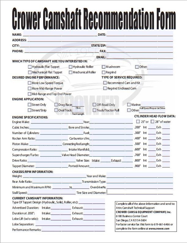
Here is the Crower Cam Shaft recommendation form which I think I'll attempt completing to the best of my ability and see what they come back with. I may need some assistance from yall to figure out some of the specs requested on the form. If I'm struggling with a concept while researching, I'll be sure to ask in the thread.
Just like what Niko's was stating in the "In depth discussion on Cam design and relation to Compression" thread in the FAQ. Head flow plays an important roll. So far up to page 8 of that thread. Wish it had more of the math visible. I realize a lot is done in software programs so the designer might not have to be intimately familiar with the math just the program and required data. And I also know there is some history with both Niko and Rocket but it has been an interesting read overall. If nothing else it gives one a glimmer of just some of the complexities involved. There does not seem to be any one straight cut answer. Seems to be a complex web all interconnected, one change affects a great many things.
Anyways, what ever you do, don't hold your breath on this. I won't be making larges amounts of progress on this for a few different reasons. I'll keep plodding along when and where I can and keep updating this thread as I go.
Trying to find flow data on the stock Y8 head. Found a site that had it for both stock and ported but the cached version on goggle shows the pics are broken.
I noticed the asymmetrical bowl design of the head and thought it was to promote swirl. Which explains why everywhere I look they say the Y8 doesn't flow as well as the Z6 with it's tumble ports. Swirl is better for low and mid range power and fuel efficiency/mpg is what I've been reading. It seems porting the Y8 it will flow in range with a ported Z6. I suspect the porting removes the asymmetrical swirl promoting design and turns it into tumble ports which is geared mainly at top end power at the cost of low and mid.
The one thing I am leery about porting is it seems to be done by hand. This makes me wonder how it gets done to where the same amount of material is removed in each bowl? The thing about the cast head is the chambers are all the same with a pretty tight tolerance. Hand removing material, how do you know the valve chambers have the same tolerance to each other as stock? Efficiency will change per cylinder if the bowls are not exactly the same. I guess a special CNC machine would need to be utilized for precision porting. Not sure if that even exists.
I'm thinking for my purposes, I'd like to keep the swirl port design. Maybe the best option is to go for over sized valves. Might mean valve relief work on the pistons that are almost already non existent. I think that would allow a bit more flow at the cost of some velocity while still keeping the asymmetrical swirl port design.
Or I leave the head be, and I stick with the Stage 1 upgrade Y8 Crower cam even though I have unusally high compression ratio. Maybe drop the CR a bit with a thicker head gasket. And let the tune contend with the rest on 91 octane.
The other change is the dome pistons are upping the compression ratio but also reducing actual possible intake by shrinking the size of the cylinder cavity. I need to see what effects that tends to have on motors, changing from dish to dome.
Just so many things to think about. No wonder people just slap **** together and throw it on a dyno to see if it works or not. Doing it on paper first......
I think I am over thinking everything and I don't believe I can find all the data required for free so I think I will just proceed and test the end result and tweak from there.
I think the area that has the most flexibility to accommodate the proposed changes is the intake. I think it will help keep costs down on an already well beaten path.
Last edited by TomCat39; Apr 30, 2015 at 10:21 AM.
DO IT ON ALL FOURS
Joined: Sep 2007
Posts: 7,632
Likes: 15
From: IN Your Mind
When porting the runners / bowls you can measure two ways to be sure you are even. One being with a graduated cylinder (or some form of precision measurement device) and testing each port. The problem with this is material may not be removed in the same spots which could cause air flow issues but still measure the same volume. The other issue with that way is that not every runner will want the same material removed. For instance, if you look at some B-series VTEC headsthey have a massive dimple in only one of the runners and is completely different than the rest.
The accepted way to verify port work is to use a flow bench. Good hand porters will be modest with the port job and check each runner on the flow bench. Then they will adjust each port accordingly. A CNC port job usually just runs the preprogrammed port job. Due to casting differences, this is why you will see different amounts of cutting depths on different cylinder heads. It is preset and won't change like a hand job (LOL) will.
For the combustion chambers you CC the head. Again with a graduated cylinder and a fluid with low surface tension, you measure each one with the valves in place. Rework as necessary to make them both visually and measured the same. A CNC job will still need to be verified to due to casting differences if you want the same CC in every chamber.
You are correct on the head differences though. It all depends on the characteristics you desire from this engine. The problem with running thicker head gaskets is it increses your quench distance, which is the main benefit to a Y8 head (quench pads). Arguably they aren't needed, but it helps promote a more even burn when the correct height is set.
Honda-Tech Member
Joined: Apr 2012
Posts: 626
Likes: 0
From: Hickory, NC
Thread Starter
Hysterically Calm
Joined: Jan 2013
Posts: 10,439
Likes: 597
When porting the runners / bowls you can measure two ways to be sure you are even. One being with a graduated cylinder (or some form of precision measurement device) and testing each port. The problem with this is material may not be removed in the same spots which could cause air flow issues but still measure the same volume. The other issue with that way is that not every runner will want the same material removed. For instance, if you look at some B-series VTEC headsthey have a massive dimple in only one of the runners and is completely different than the rest.
The accepted way to verify port work is to use a flow bench. Good hand porters will be modest with the port job and check each runner on the flow bench. Then they will adjust each port accordingly. A CNC port job usually just runs the preprogrammed port job. Due to casting differences, this is why you will see different amounts of cutting depths on different cylinder heads. It is preset and won't change like a hand job (LOL) will.
For the combustion chambers you CC the head. Again with a graduated cylinder and a fluid with low surface tension, you measure each one with the valves in place. Rework as necessary to make them both visually and measured the same. A CNC job will still need to be verified to due to casting differences if you want the same CC in every chamber.
You are correct on the head differences though. It all depends on the characteristics you desire from this engine. The problem with running thicker head gaskets is it increses your quench distance, which is the main benefit to a Y8 head (quench pads). Arguably they aren't needed, but it helps promote a more even burn when the correct height is set.
The accepted way to verify port work is to use a flow bench. Good hand porters will be modest with the port job and check each runner on the flow bench. Then they will adjust each port accordingly. A CNC port job usually just runs the preprogrammed port job. Due to casting differences, this is why you will see different amounts of cutting depths on different cylinder heads. It is preset and won't change like a hand job (LOL) will.
For the combustion chambers you CC the head. Again with a graduated cylinder and a fluid with low surface tension, you measure each one with the valves in place. Rework as necessary to make them both visually and measured the same. A CNC job will still need to be verified to due to casting differences if you want the same CC in every chamber.
You are correct on the head differences though. It all depends on the characteristics you desire from this engine. The problem with running thicker head gaskets is it increses your quench distance, which is the main benefit to a Y8 head (quench pads). Arguably they aren't needed, but it helps promote a more even burn when the correct height is set.

Well, to be perfectly honest, you all are seeing much more than I.
Your inputs are greatly welcomed even if it's only in direction on helping at making this become a reality.
I'm sure I am more than capable of drifting away from that potential without even being aware of it and do so very quickly. This is where I believe your insight(s) can prove very beneficial to all.
Currently I have more formulas to get up in that table above as well as more physical data on the parts in the first table.
After that, I think I need to come up with a check list or flow chart for the work that will need to be done so no critical steps are missed. i.e. engine balancing for any weight changes.
Last edited by TomCat39; May 2, 2015 at 09:24 AM.
GDD Lonely Krew
Joined: Feb 2005
Posts: 860
Likes: 2
From: Reseda, CA, USA
Sounds like an extremely long-winded and complicated way of getting less than 170hp... It is interesting conversation at least. Better than the dead silence that has overcome this place recently.
Honda-Tech Member
Joined: Aug 2004
Posts: 4,167
Likes: 2
From: Atlanta
Love the technical stuff even though it's way over my head. Will be sitting back and reading. This is great tech. Thanks for the links as well. Goood reading.
Only thing I have to question is your calculation for peak TQ on a Y8 intake manifold being at 7200 ~7500 rpms. Is it even possible in stock form (or are you porting it?). Even with all other aspects being perfectly sized, it seems high. But I haven't done any formulas or studied this in depth like you have( big props! ).
And the" off road/race use only" . I think most companies put that on there just to cover their asses. I wouldn't let the name alone stop you from considering it on a street setup.
Great to see this kinda tech around.
Honda-Tech Member
Joined: Aug 2004
Posts: 4,167
Likes: 2
From: Atlanta
Honda-Tech Member
Joined: Apr 2012
Posts: 626
Likes: 0
From: Hickory, NC
haha
Tomcat skunk2 is now offering their ultra series intake manifolds for d series. i would definitely look into this, over the skunk2 pro series, stock y8 intake, or performer x
Tomcat skunk2 is now offering their ultra series intake manifolds for d series. i would definitely look into this, over the skunk2 pro series, stock y8 intake, or performer x
Last edited by whitesihatch; Apr 30, 2015 at 05:05 PM.
Thread Starter
Hysterically Calm
Joined: Jan 2013
Posts: 10,439
Likes: 597
Love the technical stuff even though it's way over my head. Will be sitting back and reading. This is great tech. Thanks for the links as well. Goood reading.
Only thing I have to question is your calculation for peak TQ on a Y8 intake manifold being at 7200 ~7500 rpms. Is it even possible in stock form (or are you porting it?). Even with all other aspects being perfectly sized, it seems high. But I haven't done any formulas or studied this in depth like you have( big props! ).
And the" off road/race use only" . I think most companies put that on there just to cover their asses. I wouldn't let the name alone stop you from considering it on a street setup.
Great to see this kinda tech around.
Only thing I have to question is your calculation for peak TQ on a Y8 intake manifold being at 7200 ~7500 rpms. Is it even possible in stock form (or are you porting it?). Even with all other aspects being perfectly sized, it seems high. But I haven't done any formulas or studied this in depth like you have( big props! ).
And the" off road/race use only" . I think most companies put that on there just to cover their asses. I wouldn't let the name alone stop you from considering it on a street setup.
Great to see this kinda tech around.
And by the looks, this stuff is a bit over my head but I'm enjoying (usually) the challenge of learning it. I'm hoping for some assistance from members here to get a better understanding. Thanks go out to all who is participating as every comment seems to give some sort of insight. Even the slightest piece makes a difference in understanding.
So getting back to the crutch of it all... On my way home from work driving, I realized... I'm getting ahead of myself. More than one person stated you start with the cam and build from that. I just clued in... You have a Head and you have a Block, that's the canvas, everything else is where the flexibility is. So now, lets look at choosing the cam.
I've read till my eyes bleed and my brain leaks about cams and I still am not sure how you choose your cam.
| Part Number | 63441Y | Part Number | 63441YT | Part Number | 63442Y |
| Engine Make | Honda / Acura | Engine Make | Honda / Acura | Engine Make | Honda / Acura |
| Year | 1992-2000 | Year | 1992-2000 | Year | 1992-2000 |
| Part Class | Camshaft | Part Class | Camshaft | Part Class | Camshaft |
| Camshaft Name | Stage 1 | Camshaft Name | Stage 2 - Forced Induction Special | Camshaft Name | Stage 2 - 3/4 Race |
| Camshaft Series | Original | Camshaft Series | EFI, Forced Induction & NOS | Camshaft Series | Original |
| Engine Type | 4 Cylinder | Engine Type | 4 Cylinder | Engine Type | 4 Cylinder |
| Engine Size | D16Z6 & D16Y8 | Engine Size | D16Z6 & D16Y8 | Engine Size | D16Z6 & D16Y8 |
| Valve Lash | .006" intake and .008" exhaust | Valve Lash | .006" intake and .008" exhaust | Valve Lash | .006" intake and .008" exhaust |
| Lobe center | 110 | Lobe center | 108 | Lobe center | 110 |
| Rocker Ratio: Intake / Exhaust | 1.6 / 1.8 | Rocker Ratio: Intake / Exhaust | 1.6 / 1.8 | Rocker Ratio: Intake / Exhaust | 1.6 / 1.8 |
| Advertised Duration (.010") Intake at the Valve: Primary / Vtec / Secondary | 293 / 292 / 293 | Advertised Duration (.010") Intake at the Valve: Primary / Vtec / Secondary | 293 / 312 / 293 | Advertised Duration (.010") Intake at the Valve: Primary / Vtec / Secondary | 295 / 319 / 295 |
| Advertised Duration (.010") Exhaust at the Valve: Primary / Vtec / Secondary | / 302 / | Advertised Duration (.010") Exhaust at the Valve: Primary / Vtec / Secondary | / 318 / | Advertised Duration (.010") Exhaust at the Valve: Primary / Vtec / Secondary | / 310 / |
| Duration @ .050 Intake at the Valve: Primary / Vtec / Secondary | 197 / 228 / 197 | Duration @ .050 Intake at the Valve: Primary / Vtec / Secondary | 197 / 234 / 197 | Duration @ .050 Intake at the Valve: Primary / Vtec / Secondary | 204 / 235 / 204 |
| Duration @ .050 Exhaust at the Valve: Primary / Vtec / Secondary | / 208 / | Duration @ .050 Exhaust at the Valve: Primary / Vtec / Secondary | / 217 / | Duration @ .050 Exhaust at the Valve: Primary / Vtec / Secondary | / 223 / |
| Lobe Lift Intake: Primary / Vtec / Secondary | .205 / .254 / .205 | Lobe Lift Intake: Primary / Vtec / Secondary | .205 / .269 / .205 | Lobe Lift Intake: Primary / Vtec / Secondary | .205 / .270 / .205 |
| Lobe Lift Exhaust: Primary / Vtec / Secondary | / .214 / | Lobe Lift Exhaust: Primary / Vtec / Secondary | / .237 / | Lobe Lift Exhaust: Primary / Vtec / Secondary | / .242 / |
| Gross Lift Intake: Primary / Vtec / Secondary | .328 / .406 / .328 | Gross Lift Intake: Primary / Vtec / Secondary | .328 / .430 / .328 | Gross Lift Intake: Primary / Vtec / Secondary | .332 / .432 / .332 |
| Gross Lift Exhaust: Primary / Vtec / Secondary | / .385 / | Gross Lift Exhaust: Primary / Vtec / Secondary | / .427 / | Gross Lift Exhaust: Primary / Vtec / Secondary | / .436 / |
| Rocker Ratio Intake: Primary / Vtec / Secondary | 1.8 / 1.6 / 1.6 | Rocker Ratio Intake: Primary / Vtec / Secondary | 1.8 / 1.6 / 1.6 | Rocker Ratio Intake: Primary / Vtec / Secondary | 1.8 / 1.6 / 1.6 |
| Rocker Ratio Exhaust: Primary / Vtec / Secondary | 1.8 / 1.6 / 1.6 | Rocker Ratio Exhaust: Primary / Vtec / Secondary | 1.8 / 1.6 / 1.6 | Rocker Ratio Exhaust: Primary / Vtec / Secondary | 1.8 / 1.6 / 1.6 |
| Low RPM | Idle | Low RPM | Idle | Performance Level | 4 |
| Peak HP | 7200 | Peak HP | 8000 | Low RPM | 1000 |
| Redline | 7700 | Redline | 8500 | Peak HP | 7500 |
| Redline | 8000 | ||||
| Part Number | 63443Y | 63444YT | |||
| Engine Make | Honda / Acura | Advertised*Duration @ .010” Lift:*312�/318�*RR:*1.6/1.8*Gross Lift:*.269”/.237”*LSA:*112�*RPM:*Idle to 8000*Redline:*8500 | |||
| Year | 1992-2000 | ||||
| Part Class | Camshaft | ||||
| Camshaft Name | Stage 3 - Full Race | ||||
| Camshaft Series | Original | ||||
| Engine Type | 4 Cylinder | ||||
| Engine Size | D16Z6 & D16Y8 | D16Y8 | |||
| Valve Lash | .006" intake and .008" exhaust | ||||
| Lobe center | 110 | ||||
| Rocker Ratio: Intake / Exhaust | 1.6 / 1.8 | ||||
| Advertised Duration (.010") Intake at the Valve: Primary / Vtec / Secondary | 295 / 329 / 295 | ||||
| Advertised Duration (.010") Exhaust at the Valve: Primary / Vtec / Secondary | / 317 / | ||||
| Duration @ .050 Intake at the Valve: Primary / Vtec / Secondary | 204 / 239 / 204 | ||||
| Duration @ .050 Exhaust at the Valve: Primary / Vtec / Secondary | / 226 / | ||||
| Lobe Lift Intake: Primary / Vtec / Secondary | .210 / .276 / .210 | ||||
| Lobe Lift Exhaust: Primary / Vtec / Secondary | / .260 / | ||||
| Gross Lift Intake: Primary / Vtec / Secondary | .332 / .442 / .332 | ||||
| Gross Lift Exhaust: Primary / Vtec / Secondary | / .468 / | ||||
| Rocker Ratio Intake: Primary / Vtec / Secondary | 1.8 / 1.6 / 1.6 | ||||
| Rocker Ratio Exhaust: Primary / Vtec / Secondary | 1.8 / 1.6 / 1.6 | ||||
| Performance Level | 5 | ||||
| Low RPM | 1200 | ||||
| Peak HP | 8000 | ||||
| Redline | 8500 |
Now Crower has provides recommendations on all but 1 cam. However for the sake of the exercise lets say those recommendations are not there just the lifts, angles duration etc. I have purposely not included them from the website.
And lets say we want the best middle of the road cam. Either end is easy, the biggest and baddest or the smallest. They only have one to choose from.
But how do we evaluate the middle of the road cams to pick the one best suited for our goals?
Like I said earlier in this post, I've been doing a quite a bit of reading on cams, among other things and I don't recall seeing anything on this area.
We have a head, D16Y8, no springs, no valves as those are still up in the air...
We have a block, no rods, no pistons as those are also up in the air by group advise.... Pick the cam first.
I have posted up the 5 cams and all the specifics data to the cams that Crower provides. This information may likely be that is all that is available with some Cam manufacturers and it's up to us to figure out and decide what is best for us.
So for this example, the car is to be an upgraded daily driver from stock. It is not meant to be a D series drag car. If it makes it any easier we can also add the car is for modified NA class low speed autocross (60mph ish)
I figured to keep it simple, we'll just use the 5 cams provided by Crower, but the process should be able to be used to evaluate all the cams you can find on the marked for the engine head. From the info above and what we will most likely come across between cam manufacturers.... How do we evaluate the cams to pick the right one for our goals? What are the key elements? What formulas are required? Do people use some sort of program or software to evaluate? These are the things I have not really seen any information on and is my biggest stumbling block at the moment.
Last edited by TomCat39; May 2, 2015 at 09:29 AM. Reason: typo
Anti-GDD White Knight Simp
Joined: Mar 2014
Posts: 1,026
Likes: 0
From: Uvalde, Tx
I was going to say that you're getting ahead of yourself with the head porting and such, but looks like you figured it out
Port size will be completely dependant on other factors, namely displacement, compression, target rpm power band, and ultimately, of course, the camshaft. So we will have to figure all these things out first.
As far as selecting your cam: I am not nearly as well versed in this as some/most. I was thinking cam selection, especially for your type of build, could be a very simple affair. Any good cam manufacturer should have great data on and know the intended use, power capabilities, etc etc on each of their camshafts. I was thinking, you could just call several companies (S2, DDTech, Crower etc) and talk to them about their cams and what would fit what you're looking for. Of course this is just the simplest way to select to get the ball rolling, if you don't want to go that route then hopefully someone with more knowledge about cam selection will chime in.
And holy moly, you typed up a lot O_O
Thread Starter
Hysterically Calm
Joined: Jan 2013
Posts: 10,439
Likes: 597
Actually didn't type that much. Cut and Paste from website into Excel, did some formatting and then cut and paste that into the table tags. The paragraphs is all that I typed up.
When poking around around the ftlracing website I noticed they have a section concerning dynamic CR and cam selection:
index
Looks like they have all the various formulas to help decipher the build process. I was already copying the information on headers. Looks like I'll be grabbing the rest so it is not suddenly lost if the website goes missing.
I got some math to play with.... I'll post up what I figure out once I sit down and get the number crunching done.
Cut and Paste from website into Excel, did some formatting and then cut and paste that into the table tags. The paragraphs is all that I typed up.When poking around around the ftlracing website I noticed they have a section concerning dynamic CR and cam selection:
index
Looks like they have all the various formulas to help decipher the build process. I was already copying the information on headers. Looks like I'll be grabbing the rest so it is not suddenly lost if the website goes missing.
I got some math to play with.... I'll post up what I figure out once I sit down and get the number crunching done.