

OBD0 DPFI --> OBD1 Distributor Wiring?

Thread Starter
Honda-Tech Member
Joined: Jul 2004
Posts: 9,846
Likes: 0
From: VA, USA
I made this little diagram, so hopefully someone can make sense of it and fill in the blanks. That way I can get this dizzy wired up and future swappers can learn from it also.
OK, so I am putting an OBD1, TD-41 distributor on my A6. I took the male side of a dizzy plug from the junkyard and left the wires on it so that I can wire my harness to them and pretend that it never had a DPFI, OBD0 plug on it.
My engine harness is DPFI, so I added the two wires into the harness already when I swapped the A6 in. (C21 and C29) Basically, I just need to know which wire to solder to which so that instead of having an OBD0 male plug on it, I will have an OBD1 male plug on it.
The top plug is already done, that's only a 2-wire.
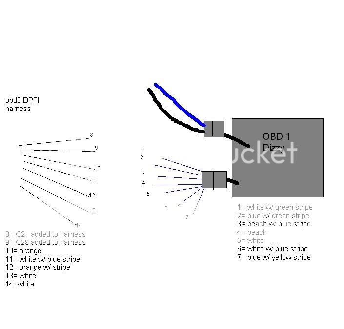
If someone can button it up like this:
8->6
9->1
12->3, etc.
That would be SO appreciated. I just couldn't find a diagram pertaining to my situation.
OK, so I am putting an OBD1, TD-41 distributor on my A6. I took the male side of a dizzy plug from the junkyard and left the wires on it so that I can wire my harness to them and pretend that it never had a DPFI, OBD0 plug on it.
My engine harness is DPFI, so I added the two wires into the harness already when I swapped the A6 in. (C21 and C29) Basically, I just need to know which wire to solder to which so that instead of having an OBD0 male plug on it, I will have an OBD1 male plug on it.
The top plug is already done, that's only a 2-wire.
If someone can button it up like this:
8->6
9->1
12->3, etc.
That would be SO appreciated. I just couldn't find a diagram pertaining to my situation.
Honda-Tech Member
Joined: May 2006
Posts: 100
Likes: 0
From: 608
Just grab a voltmeter and trace the wires from the ECU.
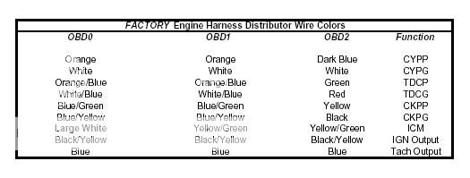
The I made the obd1 diagram below a while ago, and its 100% accurate.
The obd0 diagram should be accurate also, but i just made it.
Using the below info and voltmeter, it should be very easy to get your wiring sorted out.
Let me know if you have any other questions.
OBD0......OBD1
------------------
[b10].......[b11] --> cyp P aka cylinder position
[b12].......[b12] --> cyp M aka cylinder position
[c3].........[b13] --> tdc P aka top dead center
[c4].........[b14] --> tdc M aka top dead center
[c1].........[b15] --> ckp P aka crank position
[c2].........[b16] --> ckp M aka crank position
[b15].......[a21] --> Ignitor signal
Honda-Tech Member
Joined: May 2006
Posts: 100
Likes: 0
From: 608
I took that out of https://honda-tech.com/zerothread?id=1349052 thread. That's what i used.
Thread Starter
Honda-Tech Member
Joined: Jul 2004
Posts: 9,846
Likes: 0
From: VA, USA
Thanks to this diagram, I have figured most of it out (I think.)
However, the C1 and C2 (C21, C29) wires are still undecided.
The CKPG goes to blue/yellow,
the CKPP goes to blue/green.
Which wire is the CKPG and which is the CKPP?
However, the C1 and C2 (C21, C29) wires are still undecided.
The CKPG goes to blue/yellow,
the CKPP goes to blue/green.
Which wire is the CKPG and which is the CKPP?
Trending Topics

Thread Starter
Honda-Tech Member
Joined: Jul 2004
Posts: 9,846
Likes: 0
From: VA, USA
Sooo... via process of elimination, I decided that:
10 ----> 4
11 ----> 6
12 ----> 3
13 ----> 5
(Large) 14 ----> 1
(C1) 8 ----> 2
(C2) 9 ----> 7
Orange - Peach
White/Blue - White/Blue
Orange/Stripe - Peach/Stripe
White - White
Large White - White/Green
CKPG (C2) - Blue/Yellow
CKPP (C1) - Blue/Green
C1 C3 C5
C2 C4 C6, etc.
There. We'll see if it works.

Honda-Tech Member
Joined: May 2016
Posts: 3
Likes: 0
Ok so I'm at the same problem I'm using a dpfi engine harness and i already did the mpfi on the inside and then did a jumper harness to obd1 ecu and I also ran a obd1 injector harness straight to my ecu... So know I just need to know has to convert my dpfi harness to my obd1 dizzy I already ran the 2 wires out the fire wall Any help on this

Honda-Tech Member
Joined: Feb 2008
Posts: 45,214
Likes: 59

Thread
Thread Starter
Forum
Replies
Last Post
jtroy917
Honda CRX / EF Civic (1988 - 1991)
7
Jun 3, 2007 02:54 PM
mahatma
Honda CRX / EF Civic (1988 - 1991)
7
Jun 9, 2006 04:14 AM
Ruby Civic
Hybrid / Engine Swaps
10
Dec 11, 2003 04:07 AM