

DIY: DC5 to es1 sidemarker (custom wiring)

Thread Starter
Honda-Tech Member
Joined: Mar 2008
Posts: 48
Likes: 0
From: winnipeg, mb, canada
i just followed this thread for the dimensions didn't get the chance to take pictures while im cutting a hole on the fender
https://honda-tech.com/zerothre...75401
and this for the dc5 template
http://forums.clubrsx.com/show...ber=3
now i did a custom wiring on my sidemarkers (coz' it's much cheaper)
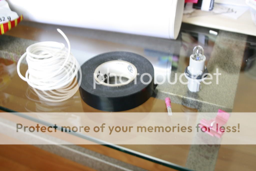
first you need this stuff
*size 20 wire
*electrical tape
*22-18 AWG female connectors
*22-18 or 18-14 AWG self stripping tap connectors
cut a wire around (depends how long or short you want) i did 11" on mine then splice the other end connect it to the female connector and use longnose to tighten up the connector
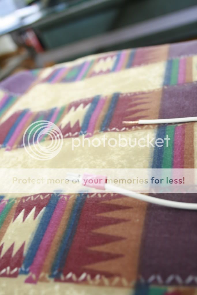
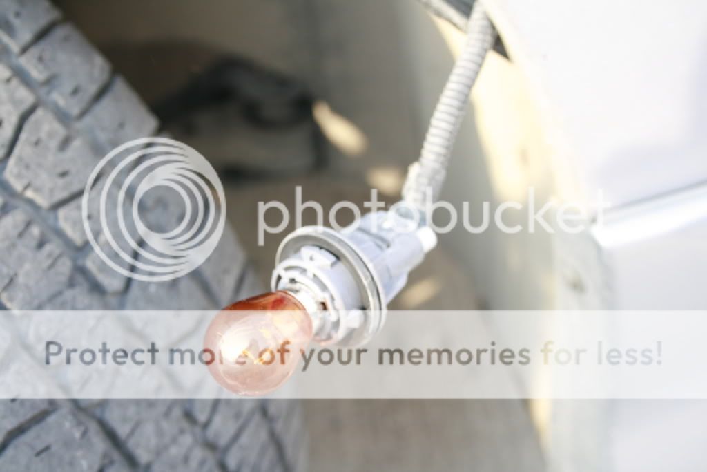
then when all 4 wires are done put the female connector on the plug on the bulb (depends how you want to put it)
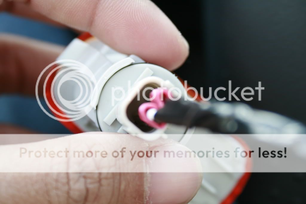
then put electrical tape on the wires
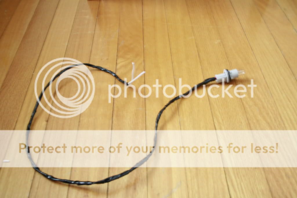
then when the two bulbs are done... now we are ready to connect it...
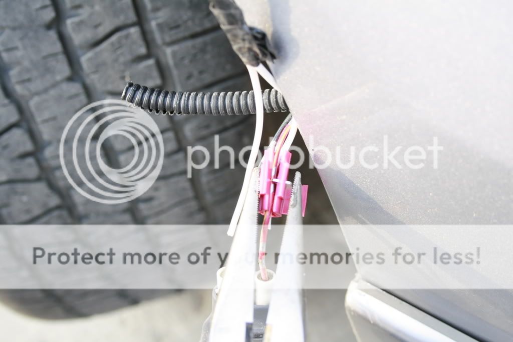
remove the sef tapping screws to open the fender liner to get the corner lights
just remember
If you want turn signal ONLY, you would put the two wires on Red & Black.
If you want running lights only, put on the Green & Black.
If you want both turn signal running lights, put it on the Red & Green.
i did the both thing so put one wire from the sidemarkers on the red one using the tap connector and the other to the green
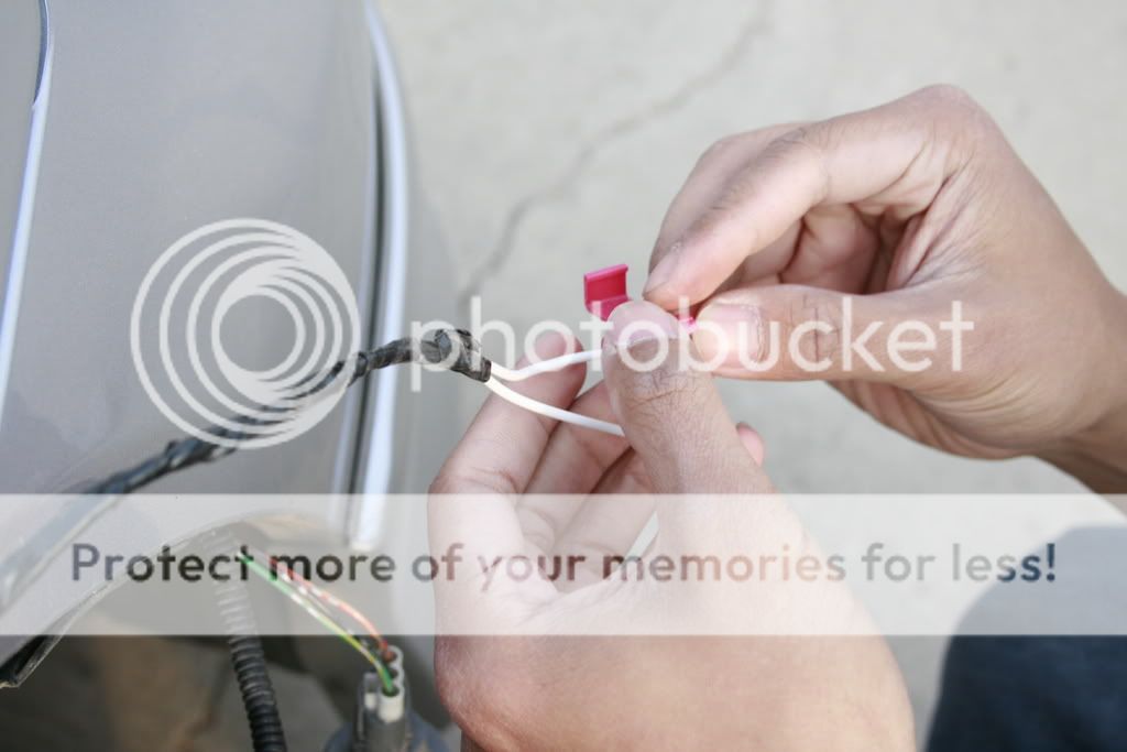
then again use longnose to make it tight
it's up to you if you want to make it look pro or not....
then wa..la... dc5 sidemarkers on my es1

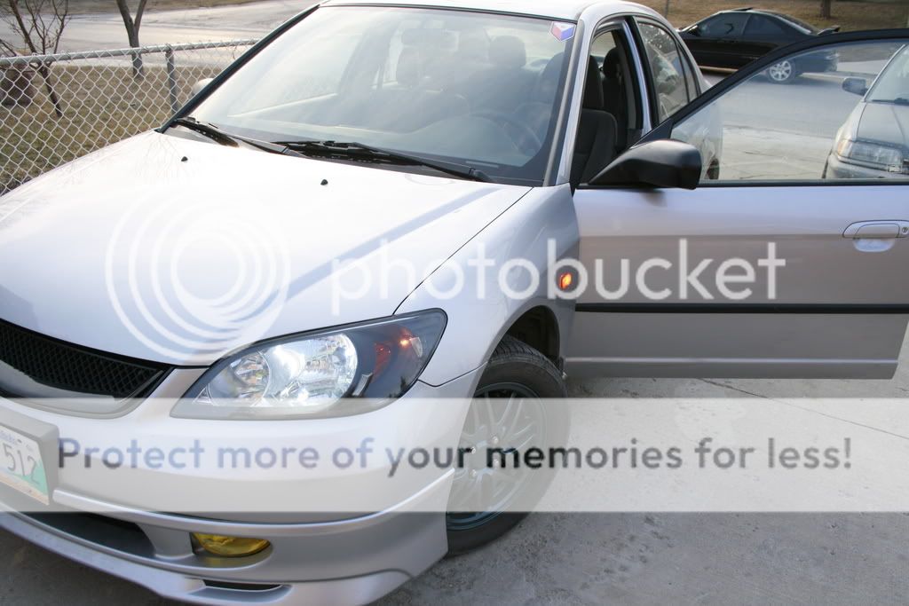
hope this thread helps even if it doesnt look pro
https://honda-tech.com/zerothre...75401
and this for the dc5 template
http://forums.clubrsx.com/show...ber=3
now i did a custom wiring on my sidemarkers (coz' it's much cheaper)
first you need this stuff
*size 20 wire
*electrical tape
*22-18 AWG female connectors
*22-18 or 18-14 AWG self stripping tap connectors
cut a wire around (depends how long or short you want) i did 11" on mine then splice the other end connect it to the female connector and use longnose to tighten up the connector
then when all 4 wires are done put the female connector on the plug on the bulb (depends how you want to put it)
then put electrical tape on the wires
then when the two bulbs are done... now we are ready to connect it...
remove the sef tapping screws to open the fender liner to get the corner lights
just remember
If you want turn signal ONLY, you would put the two wires on Red & Black.
If you want running lights only, put on the Green & Black.
If you want both turn signal running lights, put it on the Red & Green.
i did the both thing so put one wire from the sidemarkers on the red one using the tap connector and the other to the green
then again use longnose to make it tight
it's up to you if you want to make it look pro or not....
then wa..la... dc5 sidemarkers on my es1
hope this thread helps even if it doesnt look pro

 thanks
From ClubRSX:
Image: http://i28.tinypic.com/2aabrrn.jpg
Sidemarker Installation Instructions: (estimated time 4-6 hours)
First read over the entire instructions once before starting. If you do not have the experience or you don't understand the instructions or have the proper tools, DON'T do it. These instructions are offered "AS IS" and are for reference only. Verify that every step is applicable to your car. Also be warned that cutting holes in you fender may void the warrantee on that the fender.
These instructions are for use with the JDM Type R sidemarkers on a 2002 Acura RSX. ITEM#: OAS-SMDC5 PRICE: $56.95
http://www.optauto.com/webstor...smdc5
NOTE: Both of my lights were identical. There wasn't a left and right version. The driver side has the printing correct and the passenger side has the printing upside down. So I must have 2 LEFTs. Check your lights BEFORE proceeding and make any necessary changes to these instructions. You may have to flip the template accordingly. You could have a left and right hand version, you could have 2 lefts (these instructions) or 2 rights.
The first thing that needs to be done is to determine the mounting location. I have studied several pictures of Honda Type Rs to determine the location that is specified here.
* So, use a string and tape it on your car following the accent line that runs through the door handle. Following this line, extend the string to the front fender and tape it near the wheel well. (see photo #1)
Next you will need to determine the cut out location.
* First print the template (attached ZIP file) AND verify the cutout against your lights for accuracy (both of my lights were identical, not a Left or Right hand version, so one light got installed with the writing on the lens right side up and the other upside down - this means the key/notch will flip).
* Using the cutout template, cut or fold the template along the "Accent line"
NOTE: Two templates are provided, one for Driver side and one for Passenger side. Make sure to use the correct one for the side you are working on and maintain the FRONT and UP references.
* Now position the template to align the top with the Accent line and the Fender line. This should place the bottom of the cutout hole at approximately 2- 1/16" and the center rear edge of the cut-out approx. 1-5/8" form the edge of the fender. (see Photo #2)
Now you need to apply masking tape under and around the template area to avoid scratching the paint when drilling and sawing.. You only need one layer but make sure you tape up a big enough area to be on the safe side. (see photo #3)
* After the tape is in place then transcribe the cutout from the template to the tape using a pen.
Give everything a double check. Is the template facing the correct way? Is the keyway in the correct location? If you have things positioned correctly then the sidemarkers will end up with the large tapered portion facing forward. Note the lens of the markers have an arrow, this arrow will point to the front.
AND, one last thing BEFORE you start cutting: remove the fender liner and check that there are no wires in the way and the sidemarker will not interfere with anything. You do not have to completely remove the liner. Just take enough of the mounting screws and clips to free the rear and top portions (see Photo #8). If you have aligned the template correctly there shouldn?t be any problems. If you elect to install the lights closer to the door, make sure you are clear of the other plastic liner inside the fender for the door opening.
* Now locate the center of the 3 holes to be drilled. They are shown on the template but you need to transcribe the points onto your masking tape.
* Once this is complete you can remove the template.
* Start by drilling holes in the 3 round corners of the cutout. Position the drill holes so that you can use a large size drill to make the final radius cut. Use an automatic center punch to accurately position your drill. Start with a small new or very good metal drill (1/8") and make a pilot hole.
* Next switch to a larger size drill bit (I used 3/8" for the 2 large holes and �" for the smaller hole) and open up the holes you previously drilled. If you do this correctly you will not have to make any cuts in these areas when you switch to using a saber saw. (see Photo #4)
* Before using a saber saw you should add some duct tape to the bottom of the saw to prevent scratching the painted surfaces.
* Use a new fine tooth (36 tpi) blade and finish the making the cut-out. You will find that the metal cuts very easily with this blade. Run the saw at or near full speed in order to get the smoothest cut.
When the cutout has been made you may need to trim the opening here or there. Use a small file and/or a Dremel tool. If you made your initial cuts carefully there shouldn't be much that needs to be done. Next, before fully snapping the light in, use a small file and debur the edges.
Once you have the opening exactly right to accept the light, you need to seal up the fresh cut metal edges that have become exposed.(see photo #5)
* Use some auto paint primer; you only need a tiny bit. Apply the primer around the cutout using a small brush or cotton "Q-tip". Apply 3 coats.
* At this point you can start moving the operation to the other side. Use the other template, observing the Front and Up references.
* Once you have applied three coats of primer and it has dried, apply some touch-up paint.
After completing the cutout operation for both sides, lets continue on to the electrical portion. During this time you can complete the painting operation for the other side and this will allow dry time for the paint. So, don?t get anxious and snap the lights in yet.
* Locate the large hole in the inner part of the fender. It's a little forward of the cutout. The size of the hole is just right for the large rubber grommet on the wiring harness. It was too hard to get a picture of this hole but it is easy to find, just look around a bit.
* Next, take your wiring harness, remove the connector NOT used for the light housing and add approximately 3 feet of wire to it. Solder the connections and use heat shrink to protect the connections. Then cover the exposed wires with �" split loom. Note: this step could be performed ahead of time.(see photo #6)
* Then you need to snake the wiring harness through the hole identified to take the rubber grommet and down the channel (toward the front) in the frame and out the small hole near the headlights. I found I had to use a snake as a lead for the wire.
* After pulling the wiring harness through, remove the turn signal light bulb and disconnect the wiring from it. The remove the short piece of split loom on the turn signal wire to expose the two wires you will need to tap into. Note: removing the connectors for the headlight will help with the access here. Also, removing the plastic reservoir bottle on the passenger side is a must.
* Strip away insulation on the two wires used for the turn signal. I did not cut the wires; I just strip away enough insulation so as to add my new side marker wires. I also stripped the insulation away from each wire in offset positions so that the two wires could not short out.
* Strip the insulation off your side marker wires and wrap each one of them in turn to one of the turn signal wires. Then solder them together. Add electrical tape to seal up the exposed wires. (see Photo #7)
* Slide some of the split loom over the wires just soldered and tape the loom up and seal the end as originally done.
* Now give things a test. Re-install the turn signal light and connector. Plug the end of the harness into the side marker light housing and put your ignition key in and turn the signal on. Check to see that the side marker and turn signal work. Also check your head lights to make sure you got those plugs back too.
If everything checked out ok and your paint has had plenty of time to dry, you are ready to install the sidemarker lights permanently.
* Spread some RTV or Silicon around the inside edges of the sidemarker light and then snap the light housing into the fender cutout. Make sure the tapered end of the housing faces the front.
OK, one done! Now just repeat and complete the process for the other side
Good luck, hope this helps. Photo #8 is the finished results
Modified by toyomatt84 at 12:58 AM 7/4/2008
Trending Topics
Honda-Tech Member
Joined: Mar 2007
Posts: 560
Likes: 0
From: Douglasville, Georgia, United States
Fines you should really read the posts before you post but still....
Here is the template http://forums.clubrsx.com/show...ber=3 and you are going to want to use DC5 side markers.
Here is the template http://forums.clubrsx.com/show...ber=3 and you are going to want to use DC5 side markers.
Honda-Tech Member
Joined: Jan 2009
Posts: 186
Likes: 0
From: Kingsville attending college
I had a question about the wiring... my sidemarkers came with a harness which consisted of a green wire, and black wire. I'm thinking that the black wire is for the ground. If i wanted to do that turn signal driving light combination, would i connect just the green wire from the sidemarker harness to both the red and green and then ground the black one? or do i connect the green wire from the sidemarker harness to the green and the black wire from the sidemarker harness to the red one? Thanks.
Honda-Tech Member
Joined: Mar 2004
Posts: 1,253
Likes: 0
From: Rainy, WA, United State
since your wires are green and black it wouldnt matter i used yellow wires(wich i made at home) on my harness and tapd into the red and green. 1 wire to red and 1 wire to green


Thread
Thread Starter
Forum
Replies
Last Post
CRX Lee
Road Racing / Autocross & Time Attack
7
Jan 6, 2005 10:42 AM
SPECIAL Headunit Wiring!! HELP Experts!!! Thieves CUT Original Wiring... So cannot use Wiring Harnes
sightless
Honda Civic / Del Sol (1992 - 2000)
14
Apr 27, 2004 04:43 PM