Honda Accord: How to Install Supercharger Kit
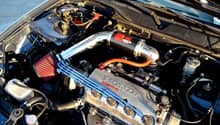
A supercharger is a pulley-driven compressor that is spun with the engine's crankshaft, compressing the air and pushing it through the intake of the engine. This article explains how to install a supercharger onto your Honda Accord.
This article applies to the Honda Accord V6 (1998-2002).
A supercharger allows an engine to produce more power without the worry of a lag in acceleration. A supercharger works by using the power of an engine's crankshaft to blow more air into the engine. The increase in air dramatically raises the horsepower of the engine. Its installation is very complicated, and involves relocating the throttle body, installing a larger pulley onto the alternator, installing a more efficient fuel pump, and rerouting several of the of engine components to fit the system. Here it is explained how to safely install a supercharger onto a 1998 to 2002 Honda Accord.

Materials Needed
- Supercharger kit
- Jack and jack stands
- Socket set
- Screwdriver
- Drain pan
- Pliers
- Razor blade
- Rotary tool set
Step 1 – Prep for installation
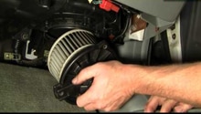
Raise your Honda Accord using a jack, and secure it by placing jack stands at the proper jacking points. Disconnect and remove the battery. On most models, the terminals use a 10mm socket for removal. Drain the coolant from the radiator, and remove all the plastic covers from under the engine. These steps can usually be achieved with a flat head screwdriver and an 8mm socket. Then, remove the plastic air intake system. The bumper will need to come off in order to access the bottom of the air box. This process requires the 10 mm and 8 mm socket, as well as a screwdriver.
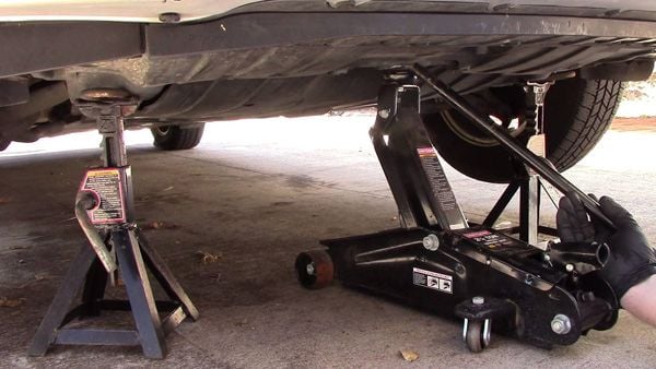
(Related Article: How to Jack Up Your Accord - Honda-Tech.com)
Step 2 – Remove the throttle body
Replace the stock upper radiator hose with the upper extended line. Then, proceed to remove the throttle body from the intake. With the intake removed (from Step 1), you should have complete access to the throttle body. On certain models there may be a coolant line attached to the throttle body, which can simply be un-clipped and moved to the side. The throttle body fasteners are easily removed with your 10mm socket.

Step 3 – Modify the alternator
Remove the alternator from the old bracket, disconnect its harness, and snake it through the top of the engine's valve cover. With the alternator removed, replace its pulley. Re-install the alternator with its new pulley and blower bracket.

Step 4 – Install the blower support brace and trim the fan shroud
The blower support brace mounts to the existing transmission lift bracket. Locate the bracket, remove the bolt, and alight the brace so it sits straight. Then, trim the fan shroud to keep it from rubbing against the blower.

Step 5 – Battery overflow installation
Install the new battery tray using the stock battery location. Place the new battery onto the tray, and connect the positive (red) terminal. Install a coolant overflow bottle in front the new battery. Also, use this time to remove the EGR valve from the system.

Figure 5. Battery installed. 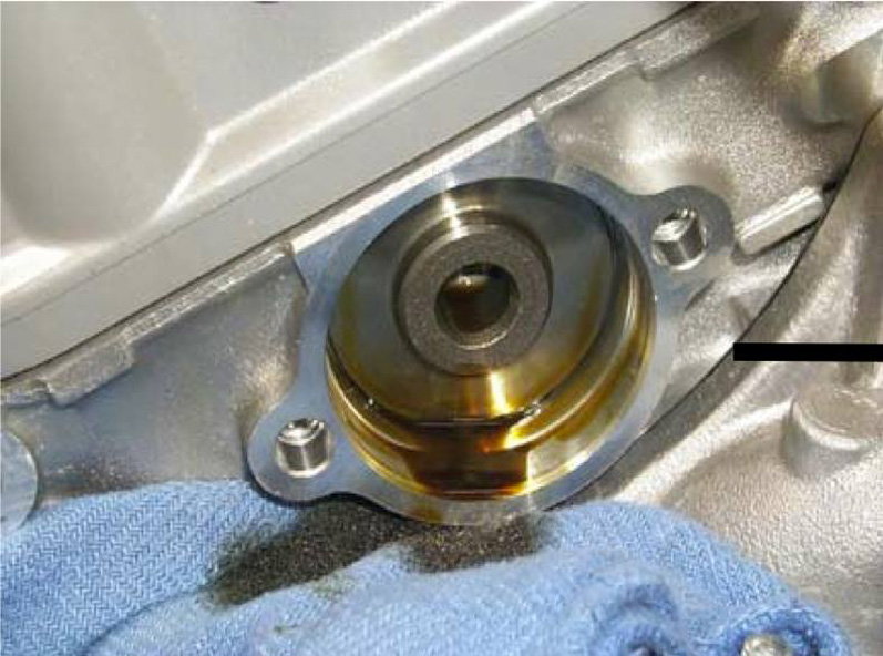
Figure 6. EGR removed.
Step 6 – Blower installation
The blower requires several mounting brackets and O-rings to be installed. First, lube and place the supplied O-ring into the blower mounting bracket. Slide the main mounting bracket to the side of the camshaft. Hand tighten the blower in place with the supplied M8x35 flange bolts, and fit the M10x40 flange bolts to their locations. Move on to the pulley side of the blower shaft, and align the blower outer bracket with the alternator bracket. Mount the blower mount to the alternator bracket, then torque (15ft/lbs) the M8x35 bolts to the head. Tighten the M10X40 flange bolts to 22ft/lbs. Torque the rest of the mount bolts to 15ft/lbs. Once finished, install the the blower belt onto the pulley.
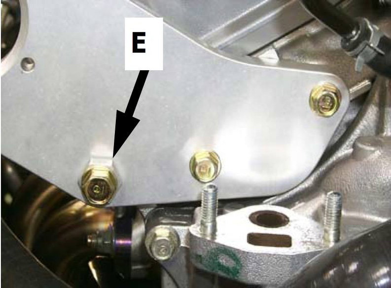
Figure 7. Blower bolts installed. 
Figure 8. Blower pulley aligned.
Step 7 – Install the power steering reservoir and fuel pressure regulator
Install the new power steering reservoir next to the pulley, and re-install the EGR. Locate the mounting hole under the cowl cover. Use it to mount the CT FPR (fuel pressure regulator), and ensure the fuel fitting is positioned towards the driver's side.

Figure 9. Power steering regulator installed. 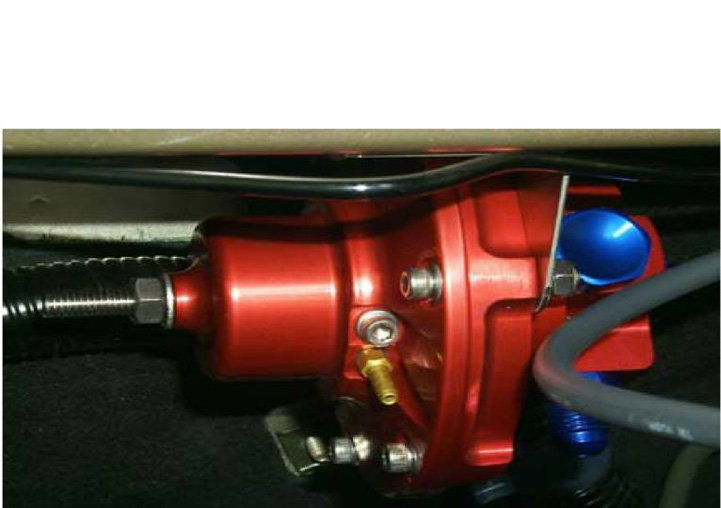
Figure 10. New CT-e fuel pressure regulator installed.
Step 8 – Remove the stock fuel pressure regulator
On the 1998 to 1999 models, the intake manifold needs to be completely removed. Remove the stock FPR, and install a size –6 (pronounced "dash 6") fuel line. Route the new fuel line into the CT-e FPR. On the 2000 to 2002 models, the intake manifold does not require removal. Remove the stock fuel pressure regulator, and install the new –6 fuel line. Route the line to the CT-e FPR. After removing the stock FPR, proceed to route the new 9-inch vacuum line to the brass fitting on the FPR. Be sure to use clamps to secure the hoses.

Figure 11. Route the new fuel line.
Step 9 – Replace the fuel pump
Access the fuel pump from the service hatch located in the trunk. Disconnect, and then pull out the old pump. Install the new unit.

Step 10 – Relocate the throttle body
Remove the studs from the old throttle body location. Re-install them onto the inlet side of the blower. Ensure the throttle cable is straight, and remove the MAP sensor. Install the MAP sensor block off plate onto the throttle body. Take the included throttle body lines and reroute them to the thermostat. Access the wiring loom to the throttle body, and route the wiring to the new sensor locations.

Figure 13. Route the throttle body lines to the thermostat. 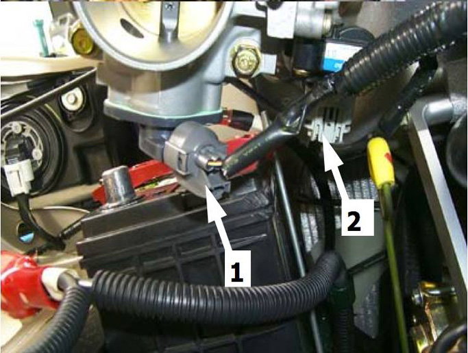
Figure 14. Route the clips to the new sensor locations.
Step 11 – Inlet manifold installation
Make sure the inlet manifold is clean of any debris. Use the supplied gasket and install it to the intake manifold. Then, mount the MAP sensor to its new location. Connect the remaining vacuum hoses to the inlet manifold.

Step 12 – Install the ice box and air filter
Mount to ice box as close as possible to the fender well. Slide the air horn over the ice box inlet, and re-install the bumper cover. Coat the filter using the supplied filter oil. Route the filter piping, and ensure that it clears the ABS sensor plug. Once done, tighten the components, install the ice box cover lid, and route the vacuum lines onto the new intake piping. Reroute the cruise control components to fit with the new system.

Step 13 – Trim engine covers and install ESM unit
Use a rotary tool to trim the engine covers, install them along with the ESM unit.

Step 14 – Prep the engine
Refill the coolant. Check all the belts, fittings and bolts. Turn the ignition on, and allow it to prime. Check for any fuel leaks on the system. If everything is good, then start the engine!

Related Discussions, and Site
- V6 Accord Options - Honda-Tech.com
- Forum Opinion on Supercharging - Honda-Tech.com
- Supercharger Installation Instructions - CT-Engineering.com