Honda Accord: How to Install a Turbocharger Kit
Learn how to install a turbocharger in order to feel the power of your Honda Accord. This helpful article will guide you in the process of adding a turbocharger kit to your Honda Accord. So continue reading!
This article applies to the Honda Accord (1990-2002).
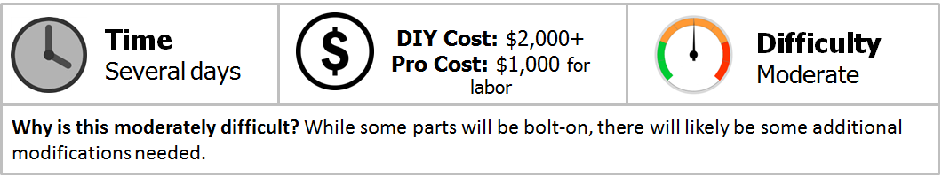
Are you looking to bring new life into your Honda Accord? Do you want to turn it into a screaming fast rocket both on and off the track? You can create a dramatic increase in horsepower (and raw speed) in one fell swoop by adding on a turbocharger kit. Although it is not the easiest job for a complete novice, it can still be done if you give yourself plenty of time as well as space to work in. Many kits are close to bolt-ons, but in almost all cases, a minimum amount of customization will need to be done. If you want to tackle this job yourself, then you will save yourself on the professional cost. If you aren't quite ready to take on this task, be sure to shop around for a good, qualified mechanic with experience in installing these kits and won't over charge you. If you are going to step up to the plate and do this yourself, read on to find out what to expect.
Materials Needed
- Metric socket set (variety of sizes)
- Metric wrench set of many sizes (the ratcheting type is highly encouraged)
- Hydraulic floor jack and jack stands
- Flat and Phillips head screwdrivers (various sizes and handle lengths)
- Wire strippers
- Dremel tool (as needed)
- Soldering tool
- WD-40, PB Blaster, or other spray type lubricant
- Eye protection
- Electrical tape
- Mulitmeter
Step 1 – Remove the air intake tube and jack up car
These should be replaced with high performance parts to maximize the benefits of the turbocharger kit. The replacements for the air intake kit is a bolt-on. Remove the two screw clamps holding the silicone coupler up at the throttle body, and the bolt at the air filter where the intake is holding onto the chassis. The intake hose should pull toward you, then up and out.
Then, jack up your car. Use a hydraulic floor jack to raise your car. Place it on jack stands in the appropriate spots. Only the front of the car needs a lift; however, you can lift both ends up onto jack stands if you like.
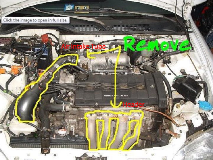
Figure 1. Remove the air intake tube. The header will be removed in Step 2. 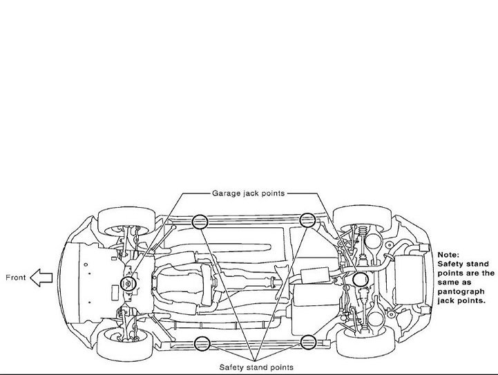
Figure 2. Raise the front end of your car, and place on jack stands.
(Related Article: How to Jack Up Your Accord - Honda-Tech.com)
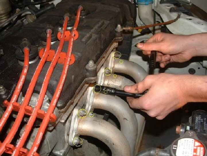
Step 2 – Remove the header
- Remove the nine 12mm nuts that hold the headers to the engine.
- Remove the three bolts that couple the catalytic converter to the exhaust.
- You now have access to remove the final two bolts of the exhaust manifold that are located behind the engine block. Once these two bolts are removed, the headers should fall right out.
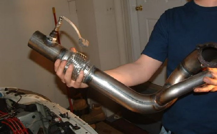
Step 3 – Remove O2 sensor from header pipe and install onto new turbo downpipe
Use some lubricant spray on the O2 sensor. It's a good idea to do this the day before to get it nice and loose to make removal easier. With the O2 sensor removed, install it onto the turbo downpipe. The downpipe is the exhaust piping just aft of the turbochargers. Take care with handling and installing the sensor onto your new downpipe bunghole.
Step 4 – Attach manifold to engine block and attach turbo to manifold
Slide the turbo manifold onto the engine block exhaust studs. Attach the turbo to the manifold, and only hand tighten the bolt initially. You want to make sure that it fits in correctly. A common issue is the engine block's web casting will get in the way. This casting can be cut away with a Dremel tool and a cutting blade. Once everything is in its place (correct and flush), tighten down all the bolts.

Figure 5. Slide the new manifold onto the engine block studs. 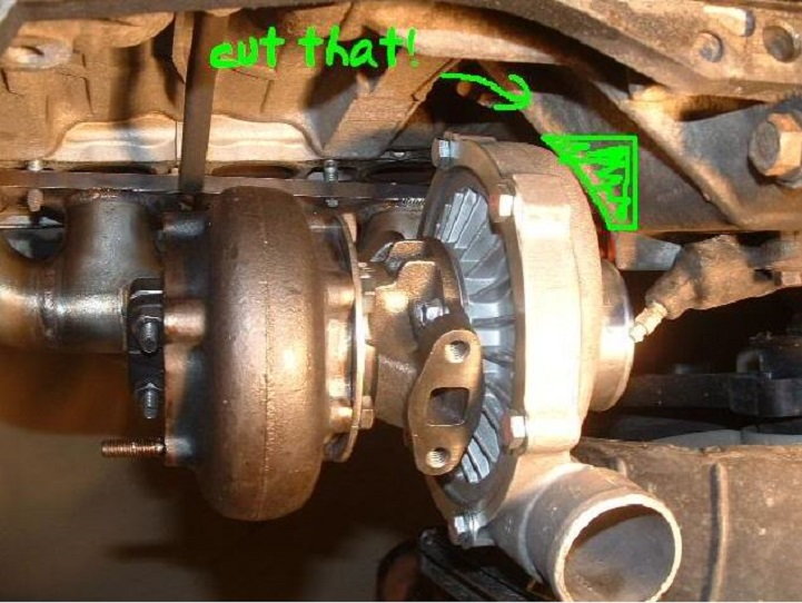
Figure 6. Cut away the web casting on the engine block to get a proper fitment.
Pro Tip
You may have to "clock" your turbo charger to fit your setup correctly. Do this before you mount it onto the manifold. Simply loosen the bolts that hold the turbine housing to the center housing, rotate until it is in the correct placement, and then re-tighten.
Step 5 – Install the oil drain line
If your turbocharger kit did not come with an oil drain line kit, you will need to purchase one for this step.
- Drain the oil from your engine via the normal method of removing the drain plug (17mm) from the bottom of the drain pan.
- After the oil is drained, remove the flywheel cover plate where the tranny meets the block (next to the pan).
- When that plate is removed, you will find about four more bolts along with all the rest (about 26 total) that hold the pan up. Remove all of them.
- Either cut and weld on an oil drain bunghole, or drill a hole into the oil pan at the highest part you can (over the deepest section of the oil pan). This will ensure a good flow of cooling oil to the turbocharger.
- Use all the materials such as rubber gaskets and seals, or what came with the oil line kit to make sure you don't create any oil leaks.
- Make sure that the oil line always flows downhill to the pan.
- Once the line is secured to the pan, re-install the oil pan to the car.
- Use the oil drain flange and gasket included with the oil drain kit to attach them to the turbocharger.
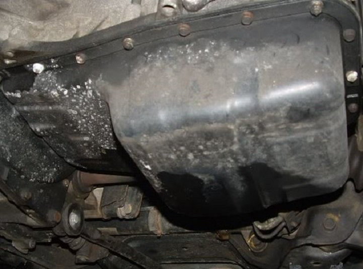
Figure 7. There are lots of mounting bolts to be removed to get the oil pan out. Make sure you drain all the oil first. 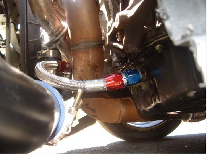
Figure 8. The completed oil line project will resemble something like this.
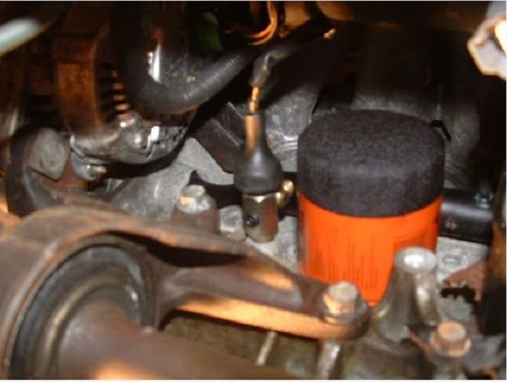
Step 6 – Install the oil feed line
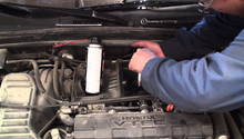
Remove the stock oil pressure sensor plug that is mounted to the back of the engine block just to the left of the oil filter. It should snap out with just a little force, not much. Once that plug is out, you'll see the oil pressure sensor that it covered. Remove the sensor with a 21mm deep well socket. You will replace the stock pressure sensor with the oil "T" that you got in your kit. It has three holes in it, and the kit also supplied one hex nut bolt to plug one of those holes (if you are not using an aftermarket oil pressure sensor that would use it).
- Take great care in screwing the oil "T" into the block where the stock oil pressure sensor was. If you screw it in too tight, you can crack your block.
- Once the oil "T" is in place, screw the stock sensor into it, and into the hole on the backside. The other hole you will plug with the little hex bolt.
- Take the small "ss" line that came in your oil line kit, and firmly (but not too tightly) thread it into the last hole on the oil "T."
- Run the oil line from the "T" up through the intake manifold runners, and over the valve covers to the turbo where you will thread it in very tightly.
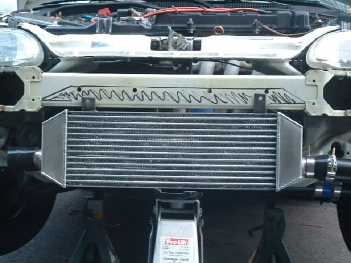
Step 7 – Install the intercooler
This is going to be the most difficult part of this whole project if you didn't get the standard intercooler and the front mount intercooler (FMIC). If you did, that is great news. You will only have to drill two holes and mount it. Most any other intercoolers will require some significant metal cutting. If you are using a rotary tool such as a Dremel with a metal cutting wheel, it is going to take up to three hours for this step alone. That is the safest way to work; however, you could also use a high speed larger tool, which is not quite as easy to use. In either case, you must wear good quality eye protection because sparks and metal shards will be flying everywhere. You first need to remove the front bumper.
- Remove the five bolts on the top of the radiator support.
- Inside each fender wheel is a single bolt that holds the bumper to the fender wheel. Remove these bolts.
- Remove the eight screws that attach the splash guards to the bumper, and set them to the side.
Step 8 – Trim the grill and splash guards (if applicable)
Depending upon the size of your FMIC, you may need to do some additional cutting to make everything fit perfectly. The grill as well as some of the splash guards may need to be cut.

Step 9 – Remove internal stock fuel pump
- Disconnect the battery terminals.
- Remove the bolt that holds the back seat to the chassis. You can reach this bolt by crawling into your trunk.
- Push the top front of the back seat up, and disengage the metal clip as well as the bracket that holds it in position.
- Once both the rear bolt and front clips are removed, pull out the back seat via the trunk.
- Open up your garage door(s) if you haven't done this already, and if you are working inside your garage.
- Open up your gas cap to relieve some pressure.
- Wrap a rag around the fuel filter, which is next to your battery to catch the escaped gas that will leak out.
- There is a service bolt on the banjo bolt (on top of the fuel filter). Turn the service bolt to release the rest of the pressure in the fuel system.
- In the rear of the car (on the floor) you will find the access panel to the gas tank. Unscrew the four screws to gain access to the fuel pump.
- Gently pull up at an angle towards your body to remove the fuel pump.
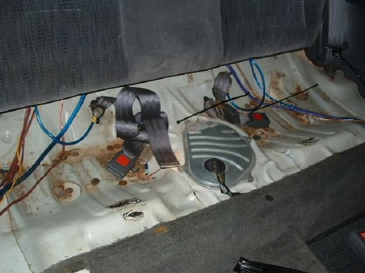
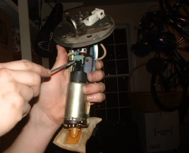
Figure 12. After removing back seat, you'll find the access to the fuel pump in the fuel tank. 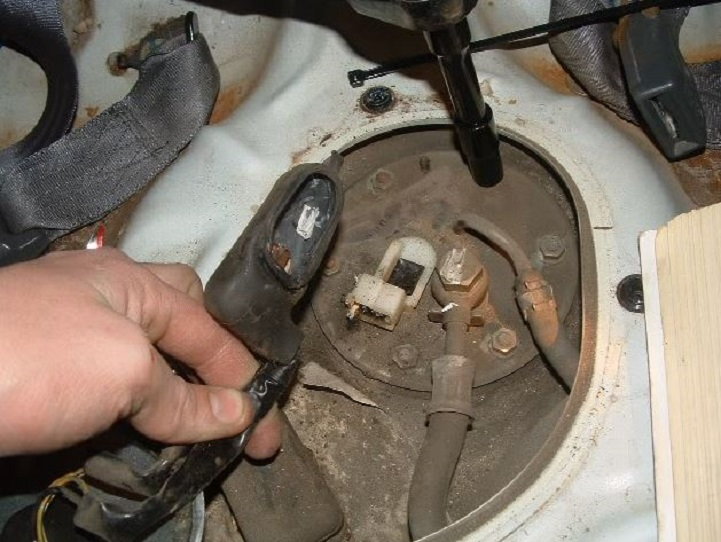
Figure 13. Pull back the rubber boot to remove the wiring harness, remove the banjo bolt, and the suction hose to prepare for fuel pump removal.
Step 10 – Connect new fuel pump and re-install
- Using a flat head screwdriver, gently pop off the green safety clip that is holding the wire plug together on the stock fuel pump.
- Use pliers to pull the rubber hose off the nipple.
- Pull the fuel pump off of the mount.
- Compare your new fuel pump with the existing fuel pump in order to ensure proper fitment.
- Install the new pump onto the mount, reattach the hose to the nipple, reattach the hose, and then snap the green safety clip back in place.
- Install the pump back into the tank, reattach everything, and then replace the access panel back into the floor.
- Re-install the back seat, starting with the front metal clip and bracket. Then, get those into place before securing the rear bolt.
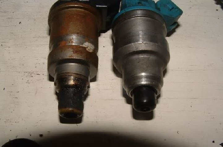
Step 11 – Install new fuel injectors
- Use a flat head screwdriver to pop the metal wire that holds the injector clips onto the stock injectors.
- Use a 10mm socket with extension to remove the three nuts that hold the fuel rail to the manifold.
- Remove the fuel rail.
- Pull the injectors out of the manifold. Do not lose the two O-rings that are below the fuel injectors.
- Cut and strip the two wires that lead back to the stock injector clips.
- Strip the ends of both sets of wires.
- The four pairs of wires and the new injector clips will each have a common color wire as well as a random color wire.
- Solder the common color wire from the existing wire with the common color from the new injector clip.
- Do the same for the random colored wires.
- The order does not matter with the spark plug wires and the distributor caps.
- Use electrical tape to cover any exposed wires.
- The new injectors will likely be wider in diameter than the stock injectors, so the existing O-rings will be too small. You will need to use O-rings that will fit these new injectors either by purchasing new ones, or boring out the existing with a Dremel tool. Purchasing new ones would be the optimal choice.
- Install the new injectors.
- Re-install the fuel rail.
Step 12 – Install fuel injector resistor box
This step is probably the most complex of this whole process. The OBD0 Hondas use low impedance injectors, and need a resistor box. You don't need to buy a new one because you can get a used one from a salvage yard or anywhere else. You will need to locate your dead end clip that sends the power to the injectors. This will likely be either on a wiring harness in the right hand corner of the engine bay, or under the intake manifold.
- Remove the cover of the dead end clip, so you can see the inside.
- There are eight ports in the dead end clip. You need a multimeter to find out which of the eight are hot, supplying power to the injectors.
- Once the hot ports are located, the corresponding wires hooked into these ports will need to be cut several inches away from the dead end clip, so that there is plenty of wire left on each piece.
- Strip both sides of the newly clipped wires. This is where the resistor box is going to tie into.
- The resistor box should have five wires coming from it; four coming to the stripped wires from the dead end connector. Match these colors 1:1, and you should have one extra random colored wire left over on the resistor box.
- Take the four common colored wires from the resistor box, and splice each one to its mate on the cut wires that lead to the injectors. After splicing, wrap with electrical tape.
- Take the single, odd man out wire from the resistor box and solder (or splice) it to all four of the cut wires that head back to the dead end connector. Wrap with electrical tape.
- Mount the resistor box inside the engine compartment.
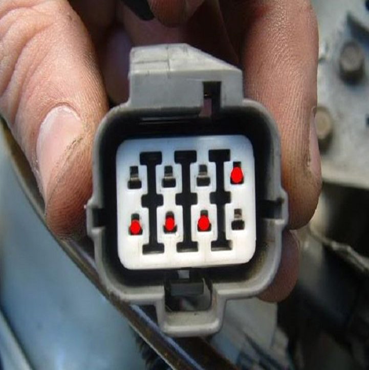
Figure 16. Find the hot wires. Don't assume they will match this picture. 
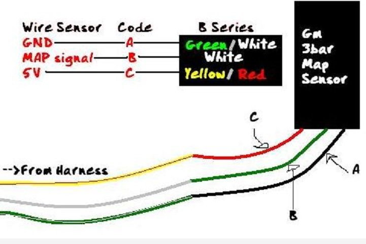
Figure 17. Rudimentary wiring diagram to follow.
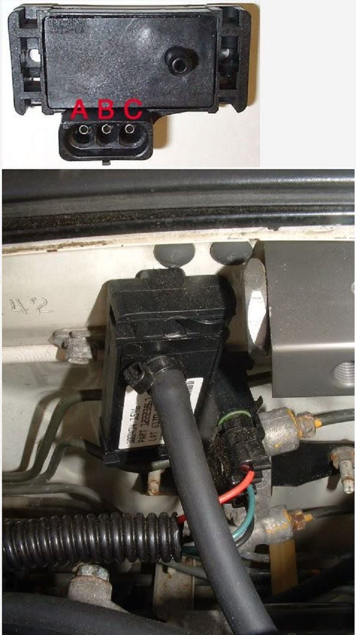
Step 13 – Install new MAP sensor
Take special care in this section as the MAP sensor is an integral component of the proper performance of your car, especially with a turbocharger installed. The stock MAP sensor will not work right with your turbocharger. For this procedure, the GM 3-Bar Map sensor with Pigtail connector is used. This particular part can be bought for less than $100.
- Find the stock MAP sensor right above the throttle body.
- Clip off the old connector on the harness side of the sensor. Strip the wires.
- Strip the wires of the Pigtail coming out of the GM Map sensor.
- Connect a vacuum hose from the map sensor to a good vacuum source like a GE vac manifold.
- Do not "T" the vacuum hose off anything else or use too long of a hose because the MAP sensor will not function properly.
- Use a multimeter to check the conductivity from A to C (at 5 volts) with car on and the engine not running. Check for 1.6 volts between A and B.
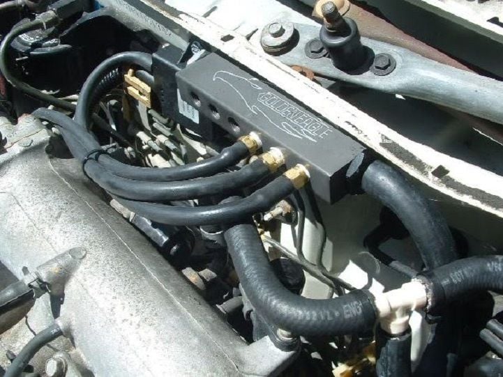
Step 14 – Install vacuum manifold
- Purchase a vacuum manifold for a great look, or if you need multiple ports.
- Purchase fittings that are 1/4" threaded side, and 1/8" barbed size.
- Use threaded tape around the threads of the fittings to ensure a good, tight seal.
- Mount the manifold no more than five inches away from the brake booster line.
- Use a 1/2" diameter vacuum line, and measure the distance it needs to be (use a larger "T" that will fit the 1/2" lines).
- Cut the brake booster line BEFORE the check valve.
- Run the 1/2" line from the "T" to the side of the manifold.
- Connect the rest of the normal sized vacuum lines from the manifold to the components that use them.
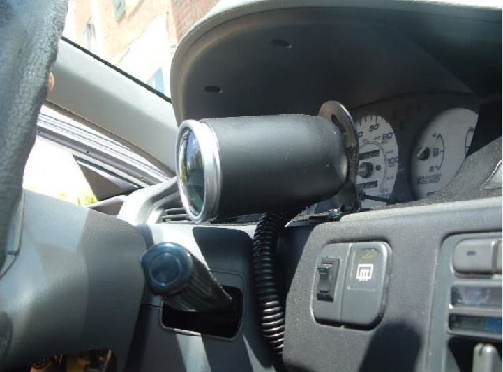
Step 15 – Install boost gauge
- Purchase a good, quality gauge to avoid faulty readings.
- Run wires directly to the fuse box for the proper power needed.
- Run your boost/vacuum line to a vacuum source. This line can be fed right through a pre-existing hole in the firewall up under your dash to your gauge.
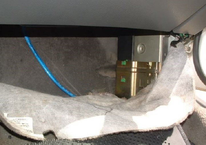
Step 16 – Install Honda ECU
- Pull the carpet up from under the dash of the passenger's side of the car.
- The existing ECU will be mounted on the side wall.
- Remove the four 10mm nuts and bolts that mount the ECU to the wall.
- Pull the ECU, and disconnect the quick connect harness.
- Plug in the new ECU to the harness to re-mount it to the wall with the existing nuts and bolts.
Step 17 – Prep your car before flight
- Replace the oil filter, and re-fill the car with the proper amount of oil.
- Flush and add new coolant.
- Double check your wiring and vacuum hoses for secure connections.
- Re-connect the exhaust/cats as applicable.
- Pull the spark plug wires, and crank the engine a couple of times to get the oil pump to flood the turbo with oil.
- Start the car, let it idle until it is completely warmed up, and check for oil as well as vacuum leaks before taking off.
- Take it out for a test drive to feel the power.

Related Discussions
- How to Turbo Charge Your Honda - Honda-Tech.com
- How Much for Turbo Install? - Honda-Tech.com