


wiring diagram question


Thread Starter
Honda-Tech Member
Joined: Dec 2009
Posts: 6
Likes: 0
From: scotland, united kingdom
anyone know what this dotted line is all about? (one next to the red line)
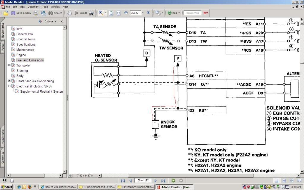
the knock sensor is a single wire sensor, grounded to the block. i dont understand what the dotted one relates to, :confused: , is it something to do with other sensor live feeds being tied in with the knock? as the line goes up to the other page it crosses through the o2 sensor, ckp,cyl and tdc sensors before grounding out at ecu pins b2 (lg2) and a26 (lg1).
im stumped as theres nothing like this in the wiring legend for the manual. :wtf:
so electrical gurus, show me what u got! lol

 , i feel a search coming on!
Honda-Tech Member
Joined: Jan 2004
Posts: 1,059
Likes: 2
From: houston, texas, usa
Here you go, better than the way I would have explained it.
http://en.wikipedia.org/wiki/Shielded_cable
http://en.wikipedia.org/wiki/Shielded_cable
Thread Starter
Honda-Tech Member
Joined: Dec 2009
Posts: 6
Likes: 0
From: scotland, united kingdom
thats a good link there. thanks again.
i take it then that the shielding on the wires of the different sensors is all joined together and only earthed at one single point on the ecu? or are they shielded also and the sheilding grounded to the chassis?
i take it then that the shielding on the wires of the different sensors is all joined together and only earthed at one single point on the ecu? or are they shielded also and the sheilding grounded to the chassis?
Thread Starter
Honda-Tech Member
Joined: Dec 2009
Posts: 6
Likes: 0
From: scotland, united kingdom
just found this thread and it answered my question
https://honda-tech.com/forums/showth...ielding+ground
this place is an info goldmine!!
https://honda-tech.com/forums/showth...ielding+ground
this place is an info goldmine!!