

Traction Bar Design

Thread Starter
Joined: Jan 2002
Posts: 182
Likes: 0
I've been searching, looking for an old topic in which FFGeoff had posted diagrams for the correct angles that traction bars should be built upon. I cannot seem to find this old topic of his.. anyone still have it around?? Any help is appreciated..
Richie
Richie
Honda-Tech Member
Joined: Apr 2001
Posts: 16,905
Likes: 3
From: Lansdale, PA
pretty much the only thing to be concerned about is
the actuall "bar" that runs from the front crossmember to the lower control arm ...... where that bar meets the front crossmember, it should be inline with the lower control arm mounting point on the subframe.
not sure if this is a "good" explanation or not..but if i knew how to draw a diagram id do it. to ease this for you.
Honda-Tech Member
Joined: Feb 2003
Posts: 794
Likes: 0
From: Duncannon, PA
<TABLE WIDTH="90%" CELLSPACING=0 CELLPADDING=0 ALIGN=CENTER><TR><TD>Quote, originally posted by 2.2Lcivic »</TD></TR><TR><TD CLASS="quote">pretty much the only thing to be concerned about is
the actuall "bar" that runs from the front crossmember to the lower control arm ...... where that bar meets the front crossmember, it should be inline with the lower control arm mounting point on the subframe.
not sure if this is a "good" explanation or not..but if i knew how to draw a diagram id do it. to ease this for you.</TD></TR></TABLE>
so are you saying that the mounting point for the "bar" at the front crossmember should be level with the inner control arm mounting point at the subframe?
Joined: Jul 2003
Posts: 30
Likes: 0
From: Chicago, IL, USA
<TABLE WIDTH="90%" CELLSPACING=0 CELLPADDING=0 ALIGN=CENTER><TR><TD>Quote, originally posted by rca90gsx »</TD></TR><TR><TD CLASS="quote">I've been searching, looking for an old topic in which FFGeoff had posted diagrams for the correct angles that traction bars should be built upon. I cannot seem to find this old topic of his.. anyone still have it around?? Any help is appreciated..
Richie</TD></TR></TABLE>
As Posted By Z10ROB Earlier in refrence to that drawing..
<TABLE WIDTH="90%" CELLSPACING=0 CELLPADDING=0 ALIGN=CENTER><TR><TD>Quote, originally posted by Z10ROB »</TD></TR><TR><TD CLASS="quote">
As for that drawing that is referenced in this post, https://honda-tech.com/zerothread?id=409201 it is not to scale (the radius arms would be 50 inches long) and if you look at the lower control arm pivots they are parallel to the vehicle center line. Look under your civic, you will see the lower control arm pivots are angled as compared to the vehicle center line. That drawing does not represent the eg suspension, it is inaccurate not to scale and only shows one view. Suspensions move in 3 dimensions not one. How can you base a conclusion on inaccurate data?
</TD></TR></TABLE>
I want a CRX tattoed on my butt
Joined: Jul 2004
Posts: 3,271
Likes: 1
From: Gtown
What about positioning of the radius rods along the crossmember, does that matter
I was curious as to how to connect these heim joints onto my custom radius rods.
Say my rod is 5/8" inner diameter and I buy 1/2" heim joints. Can I just weld a nut onto the end of the bar on both ends and thread the joint into it or will that no longer be strong enough?
I was curious as to how to connect these heim joints onto my custom radius rods.
Say my rod is 5/8" inner diameter and I buy 1/2" heim joints. Can I just weld a nut onto the end of the bar on both ends and thread the joint into it or will that no longer be strong enough?
Trending Topics
Mr. Badwrench
Joined: May 2002
Posts: 14,146
Likes: 2
From: stranger in a strange land
hope this helps, it is the install guide and gives an explination about why the other bars are so different.
http://www.full-race.com/artic...s.pdf
http://www.full-race.com/artic...s.pdf
I want a CRX tattoed on my butt
Joined: Jul 2004
Posts: 3,271
Likes: 1
From: Gtown
That was a very good read actually, going to read it again later to take more in.
Im still curious about only running the 2 front heim joints and the solid mount to the LCA at the back.
But finding the correct spot to mount the radius rods is kind of confusing me, in that full race pdf file they show something coming from the rear crossmember straight ahead into there bar in order to pick the location.
What is that all about?
I want a CRX tattoed on my butt
Joined: Jul 2004
Posts: 3,271
Likes: 1
From: Gtown
It will still have movement though, ive seen a few drag cars with the setup like that. A few companies still use that design for there honda bars, Beua's race Crx uses that design
Very curious, as to why some people have changed, and if that method will work safely and effectively for me
Very curious, as to why some people have changed, and if that method will work safely and effectively for me
I want a CRX tattoed on my butt
Joined: Jul 2004
Posts: 3,271
Likes: 1
From: Gtown
<TABLE WIDTH="90%" CELLSPACING=0 CELLPADDING=0 ALIGN=CENTER><TR><TD>Quote, originally posted by PINKS »</TD></TR><TR><TD CLASS="quote">That was a very good read actually, going to read it again later to take more in.
Im still curious about only running the 2 front heim joints and the solid mount to the LCA at the back.
But finding the correct spot to mount the radius rods is kind of confusing me, in that full race pdf file they show something coming from the rear crossmember straight ahead into there bar in order to pick the location.
What is that all about?</TD></TR></TABLE>

Joined: Oct 2000
Posts: 4,440
Likes: 2
From: Surrey, BC, Canada
<TABLE WIDTH="90%" CELLSPACING=0 CELLPADDING=0 ALIGN=CENTER><TR><TD>Quote, originally posted by dturbocivic »</TD></TR><TR><TD CLASS="quote">if you solid mount the radius rod to the control arm it wont be able to move..... even if it has the heim on the front.... its still "welded solid"</TD></TR></TABLE>
But that is how it is stock in an EF chassis! I've never understood why we need 4 heims either.
But that is how it is stock in an EF chassis! I've never understood why we need 4 heims either.
I want a CRX tattoed on my butt
Joined: Jul 2004
Posts: 3,271
Likes: 1
From: Gtown
<TABLE WIDTH="90%" CELLSPACING=0 CELLPADDING=0 ALIGN=CENTER><TR><TD>Quote, originally posted by raene »</TD></TR><TR><TD CLASS="quote">
But that is how it is stock in an EF chassis! I've never understood why we need 4 heims either. </TD></TR></TABLE>
Sure is how it is stock, thats why Im asking. Plan on orderring my heims tomorrow locally, would like a sure answer if I can go solid on my rear
But that is how it is stock in an EF chassis! I've never understood why we need 4 heims either. </TD></TR></TABLE>
Sure is how it is stock, thats why Im asking. Plan on orderring my heims tomorrow locally, would like a sure answer if I can go solid on my rear
I want a CRX tattoed on my butt
Joined: Jul 2004
Posts: 3,271
Likes: 1
From: Gtown
How exactly is a Jimfab style bar adjusted anyways?
Looking at pictures, they seem to be one solid piece of bar, milled and drilled for the LCA at one end, then tapped for the heim at the front.
If the bar is installed and locked down to the LCA how do you turn the bar up and or down the threads to make adjustments?
Looking at pictures, they seem to be one solid piece of bar, milled and drilled for the LCA at one end, then tapped for the heim at the front.
If the bar is installed and locked down to the LCA how do you turn the bar up and or down the threads to make adjustments?
Joined: Oct 2000
Posts: 4,440
Likes: 2
From: Surrey, BC, Canada
My guess for the JimFabs is to undo the heim from the crossmember and turn that!
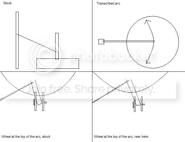
That's right dturbocivic... the only joint for the radius arms stock on EFs is flex from the bushings. And since the arm motion inscribes an arc when you view the car from the side, the inner LCA joint binds on the bushing as well, so I would think that it would actually be worse to use two heim joints and have play by the LCA.
Actually come to think of it... having a rear heim would allow the LCA to stay vertical as opposed to twisting the LCA in the bushing.
Here's a diagram of how I see it working... someone tell me if I'm on crack:
I want a CRX tattoed on my butt
Joined: Jul 2004
Posts: 3,271
Likes: 1
From: Gtown
Ive started fabbing this bar in my spare time, got me heim joints on order and they will be here anyday
One thing Ive come to a stop on is my radius rod bars. I went with a solid mount at the LCA, and instead of making something to bolt to the LCA, I simply cut off the end of the stock radius rods, stuck them into my 5/8" ID bar and welded it on.
Now with both bolts in the LCA, it holds my radius rods (at the front of the car) about 3 1/2" above my new crossbar since I went quite low with it, maybe 2" lower than stock.
I was hoping to simply heat up and bend the stock portion of the radius rod I cut off, bend them to the correct angle to meet up with the crossbar.
Was curious if that would cause any problems?
Honda-Tech Member
Joined: Jun 2004
Posts: 2,852
Likes: 0
From: Dont Steal My Car, Ct, USA
So what ur saying is that when u remove the bushing, it no longer has the flex it needs to act as a joint.
When with a hiem joint u will need them on both sides because the radiaus arms dont have that rubber they pull back on when the control arm travels up or down.
When with a hiem joint u will need them on both sides because the radiaus arms dont have that rubber they pull back on when the control arm travels up or down.
I want a CRX tattoed on my butt
Joined: Jul 2004
Posts: 3,271
Likes: 1
From: Gtown
Solid as can be
I will be able to adjust it, I will just have to remove the radius rod bolt, then twist the front heim inwards
Can I bend the bar downwards or not?
I will be able to adjust it, I will just have to remove the radius rod bolt, then twist the front heim inwards
Can I bend the bar downwards or not?
I want a CRX tattoed on my butt
Joined: Jul 2004
Posts: 3,271
Likes: 1
From: Gtown
Using 2 heim is simply cheaper and something less to worry about them breaking down and or squeeking. After my adjustments are made in the first few days, I cant see myself removing them
I want to put a bend, permanently, in the lower control arm side of the rod, so the front lines up with the crossbar and I can place my heim joint end in the rod, and everything lines up
Do I need to draw a picture?
I want to put a bend, permanently, in the lower control arm side of the rod, so the front lines up with the crossbar and I can place my heim joint end in the rod, and everything lines up
Do I need to draw a picture?

Thread
Thread Starter
Forum
Replies
Last Post