

ef civic problem code 7


Thread Starter
Honda-Tech Member
Joined: Oct 2014
Posts: 10
Likes: 0
Hey guys, this problem has me stumped. I'm in no way new to efs and hondas but can not semester to figure out this problem. My si hatch starts and idels great at first start, but under load or going down hill or stopping engine dies. Cel is on code 7 tps I replaced the tps and have ohmd it out everything is good. Until today you could drive it and start right back up when it died, now it struggles to start and has a very very long cranking condition. Any help would be great I am completely out of ideas of what it could be. Btw it has new dizzy wires plugs fuel pump main relay fuel filter and obviously tps sensor. Any one have a idea or tips I could help me out?
Thanks
Thanks

It is a voltage scalar (iirc) and I swore it was 0.5 closed and 4.5 WOT. That is probably where you are running into issues.
The official thread can be found here:
https://honda-tech.com/honda-crx-ef-...hread-2830131/
Credits to the author.
There are a lot of great threads on this site.
The official thread can be found here:
https://honda-tech.com/honda-crx-ef-...hread-2830131/
Credits to the author.
Throttle position sensor (TPS) - ( ECU Code #7 )
The Honda TPS sensor (throttle position sensor) monitors the throttle position and sends that signal to the ECU. The computer uses the TPS signal along with many other sensor inputs such as: MAP, Air Temp, Barometric Pressure, and RPM to maintain proper engine response and idle performance. Basically it is how your ECU knows your throttle input.
Electrically, Honda TPS sensors are basic variable resistors. They have a given resistance at rest and as the throttle is opened, the resistance is lowered and more voltage is sent to the ECU. This should result in a smooth increase in voltage on the output wire as the throttle is opened. The operating voltage is from 0.5v DC at rest (closed) to 4.5v DC at wide open.

Symptoms of bad TPS
Check Engine light - Code #7
Symptoms of bad TPS include hesitation/stumbling/misfiring at low RPM and poor fuel economy. It can also cause problems only at a specific throttle position. For example stumbling/hesitation only at 25% throttle but otherwise ok.
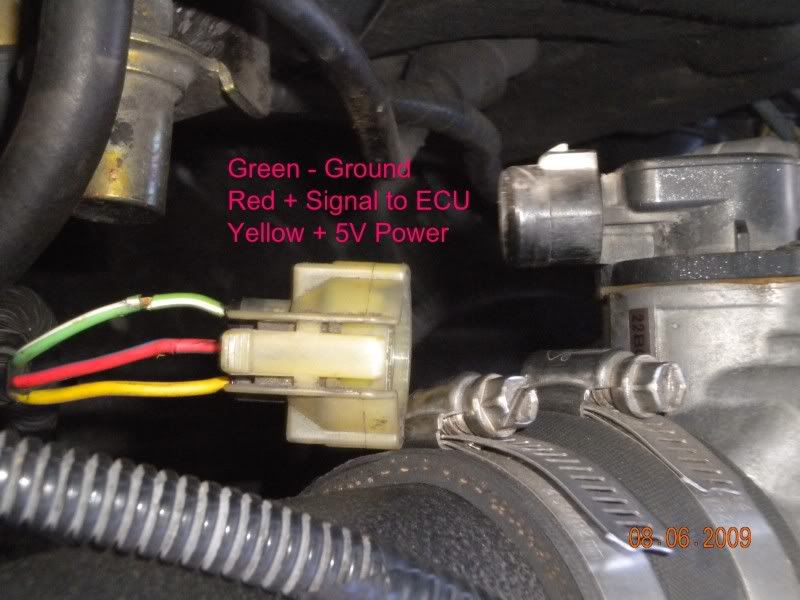
Sensor Wiring
The Honda TPS has 3 wires and you can easily check with a regular DC voltage meter or multimeter.
The GREEN wire is DC - negative ground
The RED wire is DC + Signal output to the ECU. (This is the wire we must measure for calibration)
The YELLOW wire is 5v DC + positive and should always read 5V when the key is in the ignition.
Testing TPS Voltage
Check ground - (Green)
1. Set meter to continuity ( -->I-- ). Some meters have (((( symbol which will beep when there is continuity.
2. Connect negative lead of meter to battery ground.
3. Connect positive lead to green wire. Verify that the wire has a good ground.
***Key must be in the ignition to the ACC position to test power and signal***
Check 5V Power + (Yellow)
1. Set meter to DC Voltage.
2. Connect negative lead to battery ground
3. Connect positive lead to yellow wire. Verify 5v DC +
Check TPS Signal output + (Red)
1. Set meter to DC Voltage.
2. Connect negative lead to battery ground
3. Connect positive lead to red wire. You should see approx 0.5v when closed and 4.5v when you fully open the throttle body.
4. Check the TPS voltage for “Dead Spots”. Throughout the range of movement the voltage should increase smoothly and steadily without any sudden voltage gaps, drops, or spikes .
**If your voltage is backwards (4.5v closed and .5v open) then your TPS wiring is incorrect. Reverse the position of green and yellow wires.**
**Another common mistake is reversing the TPS and MAP plugs. Make sure the correct plug is connected**
**You may have to reset the ECU to clear the CEL code 7, if you cycled the key with the TPS disconnected during testing**
(to reset ecu, disconnect neg battery cable. Remove "Hazard" 10A fuse from under hood fuse box. Count to 20. Insert fuse and reconnect battery.
TPS Removal
1. You can Remove throttle body - Disconnect intake, throttle cable, wiring plugs, and vacuum lines. Remove (2) 12mm bolts and (2) 12mm nuts. Just remember a new TB gasket.
2. To Remove TPS - some have (2) Torx screws holding on the TPS. For earlier years there are machine screws that you'll have to cut a slot in the screw head and remove with a flathead screwdriver. A dremel with a cut off wheel of a hacksaw blade work well to cut the slots.

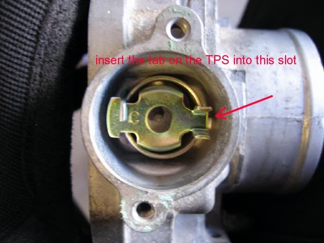
TPS Installation
1. Replace TPS - insert tab on TPS into slot on the TB and turn counter-clockwise until the bolt holes line up. Tighten the screws finger tight but loose enough where you can swivel it.
2. Reinstall throttle body and connect TPS wiring plug.
3. Connect negative meter lead to battery ground.
4. Connect positive meter lead to red signal wire and check voltage.
5. Turn TPS until you get a reading of 0.5v DC and tighten screws.
6. Verify correct voltage output. (0.5v closed and 4.5v open)

-
*********DPFI (dual injector setup) TPS**********
The TPS Sensor on the DPFI version is different than all the other types of MPFI Throttle Position Sensors. The DPFI version rotates in the opposite direction as all the MPFI versions. Because it rotates in a opposite direction, the wiring is reversed to account for this change. *If you are swapping to a MPFI setup or B-Series, you must reverse the position of the yellow and green wires.


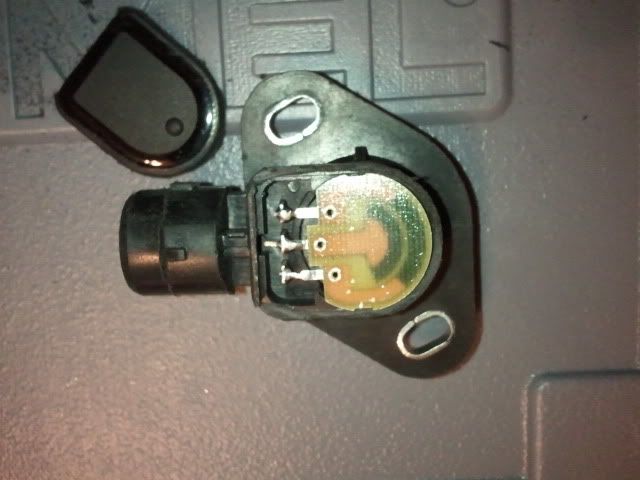
For a replacement sensor you must get a TPS for the DPFI setup because the others will not work directly. Others have disassembled the sensors and talked about some possible repairs on these threads, but nothing too substantial.
https://honda-tech.com/forums/showth...ge=2&t=2944614
Or you could buy a new one from omni power
http://thmotorsports.com/omni_power/.../i-403927.aspx
The Honda TPS sensor (throttle position sensor) monitors the throttle position and sends that signal to the ECU. The computer uses the TPS signal along with many other sensor inputs such as: MAP, Air Temp, Barometric Pressure, and RPM to maintain proper engine response and idle performance. Basically it is how your ECU knows your throttle input.
Electrically, Honda TPS sensors are basic variable resistors. They have a given resistance at rest and as the throttle is opened, the resistance is lowered and more voltage is sent to the ECU. This should result in a smooth increase in voltage on the output wire as the throttle is opened. The operating voltage is from 0.5v DC at rest (closed) to 4.5v DC at wide open.
Symptoms of bad TPS
Check Engine light - Code #7
Symptoms of bad TPS include hesitation/stumbling/misfiring at low RPM and poor fuel economy. It can also cause problems only at a specific throttle position. For example stumbling/hesitation only at 25% throttle but otherwise ok.
Sensor Wiring
The Honda TPS has 3 wires and you can easily check with a regular DC voltage meter or multimeter.
The GREEN wire is DC - negative ground
The RED wire is DC + Signal output to the ECU. (This is the wire we must measure for calibration)
The YELLOW wire is 5v DC + positive and should always read 5V when the key is in the ignition.
Testing TPS Voltage
Check ground - (Green)
1. Set meter to continuity ( -->I-- ). Some meters have (((( symbol which will beep when there is continuity.
2. Connect negative lead of meter to battery ground.
3. Connect positive lead to green wire. Verify that the wire has a good ground.
***Key must be in the ignition to the ACC position to test power and signal***
Check 5V Power + (Yellow)
1. Set meter to DC Voltage.
2. Connect negative lead to battery ground
3. Connect positive lead to yellow wire. Verify 5v DC +
Check TPS Signal output + (Red)
1. Set meter to DC Voltage.
2. Connect negative lead to battery ground
3. Connect positive lead to red wire. You should see approx 0.5v when closed and 4.5v when you fully open the throttle body.
4. Check the TPS voltage for “Dead Spots”. Throughout the range of movement the voltage should increase smoothly and steadily without any sudden voltage gaps, drops, or spikes .
**If your voltage is backwards (4.5v closed and .5v open) then your TPS wiring is incorrect. Reverse the position of green and yellow wires.**
**Another common mistake is reversing the TPS and MAP plugs. Make sure the correct plug is connected**
**You may have to reset the ECU to clear the CEL code 7, if you cycled the key with the TPS disconnected during testing**
(to reset ecu, disconnect neg battery cable. Remove "Hazard" 10A fuse from under hood fuse box. Count to 20. Insert fuse and reconnect battery.
TPS Removal
1. You can Remove throttle body - Disconnect intake, throttle cable, wiring plugs, and vacuum lines. Remove (2) 12mm bolts and (2) 12mm nuts. Just remember a new TB gasket.
2. To Remove TPS - some have (2) Torx screws holding on the TPS. For earlier years there are machine screws that you'll have to cut a slot in the screw head and remove with a flathead screwdriver. A dremel with a cut off wheel of a hacksaw blade work well to cut the slots.
TPS Installation
1. Replace TPS - insert tab on TPS into slot on the TB and turn counter-clockwise until the bolt holes line up. Tighten the screws finger tight but loose enough where you can swivel it.
2. Reinstall throttle body and connect TPS wiring plug.
3. Connect negative meter lead to battery ground.
4. Connect positive meter lead to red signal wire and check voltage.
5. Turn TPS until you get a reading of 0.5v DC and tighten screws.
6. Verify correct voltage output. (0.5v closed and 4.5v open)
-
*********DPFI (dual injector setup) TPS**********
The TPS Sensor on the DPFI version is different than all the other types of MPFI Throttle Position Sensors. The DPFI version rotates in the opposite direction as all the MPFI versions. Because it rotates in a opposite direction, the wiring is reversed to account for this change. *If you are swapping to a MPFI setup or B-Series, you must reverse the position of the yellow and green wires.
For a replacement sensor you must get a TPS for the DPFI setup because the others will not work directly. Others have disassembled the sensors and talked about some possible repairs on these threads, but nothing too substantial.
https://honda-tech.com/forums/showth...ge=2&t=2944614
Or you could buy a new one from omni power
http://thmotorsports.com/omni_power/.../i-403927.aspx
Thread Starter
Honda-Tech Member
Joined: Oct 2014
Posts: 10
Likes: 0
It is a voltage scalar (iirc) and I swore it was 0.5 closed and 4.5 WOT. That is probably where you are running into issues.
The official thread can be found here:
https://honda-tech.com/honda-crx-ef-...hread-2830131/
Credits to the author.
There are a lot of great threads on this site.
The official thread can be found here:
https://honda-tech.com/honda-crx-ef-...hread-2830131/
Credits to the author.
There are a lot of great threads on this site.

Thread
Thread Starter
Forum
Replies
Last Post
egsickz0
Honda CRX / EF Civic (1988 - 1991)
20
Feb 8, 2011 08:28 PM
d_mina
Honda Civic / Del Sol (1992 - 2000)
2
Jul 5, 2006 12:23 PM