

Installing butterflies Pt6 ECU


Thread Starter
B*a*n*n*e*d
Joined: Oct 2011
Posts: 1,022
Likes: 0
Hey guys. I just got my hands on a Pt6 ECU from the JY and wanna know how exactly you go about hooking the butterflies up. I have yet to get the vacuum box or the butterflies (mine are removed on my H23 manifold), I will sooner or later, but I first want to see if this will be worth the effort and time. Right now I have a P12 ECU with an H23 manifold with the butterflies completely removed. Question is, would it be worth putting in the butterflies or not? I am interested in hearing about this. My low end torque seems to suffer but the high end is good. Butterflies may be better but I want your opinion on it.
If you think it is well worth the effort, can you give me some tips on how to hook them up? Wiring a new ECU pin is something totally alien to me.
Thanks.
If you think it is well worth the effort, can you give me some tips on how to hook them up? Wiring a new ECU pin is something totally alien to me.
Thanks.
Thread Starter
B*a*n*n*e*d
Joined: Oct 2011
Posts: 1,022
Likes: 0
Okay guys, so I did the responsible thing and did some research, not a very hard job it turns out, I only have one question though. What does it mean when it says I have to put one of the solenoid wires to a "hot" source? I know it means you need to hook it up to power but how and where to, the battery terminal???
Also I decided i'm going to double stack the butterfly plates, all I need is 2 cb7 AC compressor bolts and 3 Civic/Prelude AC bolts... and another gasket... My only question about this is where do I put the butterflies, on the top or on the bottom?
Also I decided i'm going to double stack the butterfly plates, all I need is 2 cb7 AC compressor bolts and 3 Civic/Prelude AC bolts... and another gasket... My only question about this is where do I put the butterflies, on the top or on the bottom?
Thread Starter
B*a*n*n*e*d
Joined: Oct 2011
Posts: 1,022
Likes: 0
Okay figured out where to put the butterflies, on the top, but about the hot wire, how do I make it 'hot'?
Still would like to know if this is worth it. Going to pick up an A6 cam next Monday when I go to the JY, gonna post it on Ebay to sell cause I people want to buy them.
Still would like to know if this is worth it. Going to pick up an A6 cam next Monday when I go to the JY, gonna post it on Ebay to sell cause I people want to buy them.
Thread Starter
B*a*n*n*e*d
Joined: Oct 2011
Posts: 1,022
Likes: 0
Cause the junkyard where I live is full of Cb7's and they're gonna get taken to the crusher soon before people even grab em.
I was asking a question about the meaning of wiring the IAB solenoid wire to a 'hot' source.
Also will this be worth it over the P12 setup I have now?
I was asking a question about the meaning of wiring the IAB solenoid wire to a 'hot' source.
Also will this be worth it over the P12 setup I have now?

B*a*n*n*e*d
Joined: Dec 2008
Posts: 12,028
Likes: 5
This is actually not going to be beneficial since you would need a chipable ecu to make it optimum however since you're going to do it anyhow I'll tell you how to do the iab's.
You need to get some wire and a blue connector that is designed to tap into other wires and you will run the wire from the iab solenoid to your iacv wire and tap into it with the blue tap connector. You don't want it "hot" all the time you just want a "switched power source" which is the iacv.
You need to get some wire and a blue connector that is designed to tap into other wires and you will run the wire from the iab solenoid to your iacv wire and tap into it with the blue tap connector. You don't want it "hot" all the time you just want a "switched power source" which is the iacv.
Thread Starter
B*a*n*n*e*d
Joined: Oct 2011
Posts: 1,022
Likes: 0
This is actually not going to be beneficial since you would need a chipable ecu to make it optimum however since you're going to do it anyhow I'll tell you how to do the iab's.
You need to get some wire and a blue connector that is designed to tap into other wires and you will run the wire from the iab solenoid to your iacv wire and tap into it with the blue tap connector. You don't want it "hot" all the time you just want a "switched power source" which is the iacv.
You need to get some wire and a blue connector that is designed to tap into other wires and you will run the wire from the iab solenoid to your iacv wire and tap into it with the blue tap connector. You don't want it "hot" all the time you just want a "switched power source" which is the iacv.
Ah I see, to the iacv. what is a blue tap connector, can't I just solder it together? I promise there as a guide with pictures on Cb7tuner.com.
Trending Topics
Thread Starter
B*a*n*n*e*d
Joined: Oct 2011
Posts: 1,022
Likes: 0
Honda-Tech Member
Joined: Mar 2007
Posts: 11,399
Likes: 69
From: East Coast 506, Canada
You want to tap into the IACV's "Hot" (+) wire....
After all this time you still have not learned what wires are hot and what wires are ground? It is pretty much a universal wire colour system. If you don't know what wire colours are positive and what ones are ground, the manual will show you!
You can tap into any of the 12v switched (+/Hot on ignition) YEL/BLK wires that come off the main relay. That includes the YEL/BLK wire of the EAC/IAC valve.
Honda-Tech Member
Joined: Oct 2012
Posts: 2,000
Likes: 3
From: Minnesota
You want to tap into the IACV's "Hot" (+) wire....
After all this time you still have not learned what wires are hot and what wires are ground? It is pretty much a universal wire colour system. If you don't know what wire colours are positive and what ones are ground, the manual will show you!
You can tap into any of the 12v switched (+/Hot on ignition) YEL/BLK wires that come off the main relay. That includes the YEL/BLK wire of the EAC/IAC valve.
After all this time you still have not learned what wires are hot and what wires are ground? It is pretty much a universal wire colour system. If you don't know what wire colours are positive and what ones are ground, the manual will show you!
You can tap into any of the 12v switched (+/Hot on ignition) YEL/BLK wires that come off the main relay. That includes the YEL/BLK wire of the EAC/IAC valve.
Thread Starter
B*a*n*n*e*d
Joined: Oct 2011
Posts: 1,022
Likes: 0
You want to tap into the IACV's "Hot" (+) wire....
After all this time you still have not learned what wires are hot and what wires are ground? It is pretty much a universal wire colour system. If you don't know what wire colours are positive and what ones are ground, the manual will show you!
You can tap into any of the 12v switched (+/Hot on ignition) YEL/BLK wires that come off the main relay. That includes the YEL/BLK wire of the EAC/IAC valve.
After all this time you still have not learned what wires are hot and what wires are ground? It is pretty much a universal wire colour system. If you don't know what wire colours are positive and what ones are ground, the manual will show you!
You can tap into any of the 12v switched (+/Hot on ignition) YEL/BLK wires that come off the main relay. That includes the YEL/BLK wire of the EAC/IAC valve.
B*a*n*n*e*d
Joined: Dec 2008
Posts: 12,028
Likes: 5
I'm really tired of your bs it's obvious you're a troll so I'm not going to respond to anything you have to say anymore.
It's obvious that Ghost was right all along.
Thread Starter
B*a*n*n*e*d
Joined: Oct 2011
Posts: 1,022
Likes: 0
I went to install the ECU pin to A17 but when I looked on my plug there was already a pink wire in its place... this is strange because I have an LX 91' Wagon Auto (5 speed swapped) and was expecting the wire not to be there.
What do I do I don't want to cut into a wire that is unknown. I have checked and double checked even with the Honda manual and I am not mistaken.
This diagram is correct. At first I thought it wasn't but the manual confirmed it:
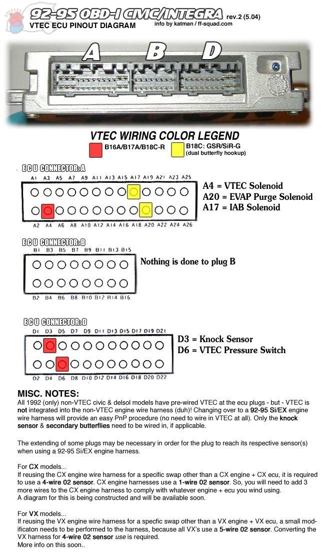
What do I do I don't want to cut into a wire that is unknown. I have checked and double checked even with the Honda manual and I am not mistaken.
This diagram is correct. At first I thought it wasn't but the manual confirmed it:
Honda-Tech Member
Joined: Mar 2007
Posts: 11,399
Likes: 69
From: East Coast 506, Canada
For **** Sakes! troll! Can't you trace the pink wire back to the strut tower connector?
If it is on the firewall side and not the engine bay side simply add it to the engine bay harness and if it's not, add it and match it up to the pink wire on the fire wall side of the connector.
It's really not that hard to trace wires. Do you have an ounce of problem solving skills? If you can't take something apart and put it back together without asking a million questions or checking the internet for affirmation. I think you should leave mechanical work to those who do posses those skills.
Thread Starter
B*a*n*n*e*d
Joined: Oct 2011
Posts: 1,022
Likes: 0
Maybe I am reading it wrong. Going by this picture, A17 is the wire (plug A is on the right) that is pink and blue. This is the wire I am talking about, its on the top on the left of the middle. Isn't this A17?

All of the pins on the plug for the top have wires; only pins on the bottom have empty spaces.
All of the pins on the plug for the top have wires; only pins on the bottom have empty spaces.
Thread Starter
B*a*n*n*e*d
Joined: Oct 2011
Posts: 1,022
Likes: 0
Okay, troll hater, I got it. What i was getting at was I was trying to see if I was misreading the diagram or if it was a bad idea to cut that pink wire and splice it in not knowing what its for... I was reading on the Cb7 forum that the A17 slot on the plug should be empty. It makes not sense that I have to cut a wire. I do not want to cut a wire on the ecu plug if I don't have to... esp if I was reading the diagram wrong.
Thread Starter
B*a*n*n*e*d
Joined: Oct 2011
Posts: 1,022
Likes: 0
I'll figure it out on my own. I think that Honda ECU just has it all upside down. I found an empty space exactly 5 spaces from the outside just like where I thought A17 was.
EDIT:
I took pics of the Honda manual:

It says A17 has a Pink/Blue wire ???

And it says A10 is Empty... This is where I put the pin. Guess i need to change that.

EDIT:
I took pics of the Honda manual:
It says A17 has a Pink/Blue wire ???
And it says A10 is Empty... This is where I put the pin. Guess i need to change that.
Thread Starter
B*a*n*n*e*d
Joined: Oct 2011
Posts: 1,022
Likes: 0
AAARRGH. I just wired everything up and installed the little black box and what do you know, the butterflies won't close on idle. I even tried using another black box and still nothing... It could be that both of them are bad... Oh well, all I did is hook up actuator to vacuum.
At the ECU plug I just snipped the pink/blue wire and wired in the pink wire for the solenoid. Do you guys think I should have hooked up all 3 wires, I mean pink/blue pink/blue - pink so that the wire I snipped still works? Cause maybe that has something to do with it, maybe its like a ground or something.
Let me tell you the results though. This is with the double stack; IAB's on top spacer on the bottom. It wasn't as good as I was expecting it to be but it was at least 5hp. I think I will install the P12 ECU again see how it runs.
Hooked up to vacuum, when is it that the butterflies open up at, i'm curious to know.
Thread Starter
B*a*n*n*e*d
Joined: Oct 2011
Posts: 1,022
Likes: 0
I literally went through like 3 different black boxes and solenoids, even using the solenoid and black box for the stock intake and it still doesn't work.
Its presumed to be hooked up properly, the black wire goes to power and the pink wire goes to the ecu pic A17. I soldered them up well enough.
Even switching ecu's to a p39 did not work.
Someone on the Cb7 tuner forum said to put the black wire an empty space in the fusebox so i'm gonna try that instead. I think I have fauly wiring when i spliced into the iacv. It must not be getting power, it has ground.
Ghost, btw I was looking at cb7tuner and saw that you said something about how in japan the ecus are opposite, that the ground is the black wire and the power wire is the pink wire, this was only for OBD II ecu's correct? I wanna get this straight cause I got a p39.

Thread
Thread Starter
Forum
Replies
Last Post