

98 Integra - horn not working

Thread Starter
Honda-Tech Member
Joined: Jul 2005
Posts: 101
Likes: 0
From: Hawai'i
It's time for my annual safety check inspection so I put my car into its "stock" settings. I have a quick release set up in my car, but that wouldn't pass. So I put my stock steering wheel and everything back in. The horn worked last night, but when my friend moved my car in the parking lot he couldn't turn right all the way. When he tried to turn left it went all the way, he then turned right again and it was fine. At this time the horn still worked.
Later that night we went to visit a friend at his work (driving there I had full turning radius). Upon leaving, when turning the steering wheel to the right there was a "click" sound that came from the steering wheel. It was until then the horn stopped working.
This morning I've spent nearly 4 hours checking fuses, wire connections, a different steering wheel, and the horn relay and cannot figure out why my horn doesn't want to work anymore. There is no clicking sound or anything coming from the horn unit itself when I press the button, so it must not be getting power or something. I have no connections to getting a safety inspection, otherwise I wouldn't have bothered putting my car back to "stock."
Any help would be appreciated.
Old Fart
Joined: May 2004
Posts: 26,173
Likes: 18
From: kelowna, bc, canada
Find the blue/green lead in steering column wiring harness, supply a ground to it, if horn works, then vrrodri is correct, the clock spring, [cable reel] is broken, they break easily if not installed properly. 94
Thread Starter
Honda-Tech Member
Joined: Jul 2005
Posts: 101
Likes: 0
From: Hawai'i
Is this the cable reel you are refering to? This is the snap I probably heard.
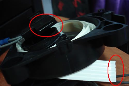
No idea how to get these things connected back together now... really dont wanna buy a new one. I only need my horn to work for like 30 seconds, haha.
No idea how to get these things connected back together now... really dont wanna buy a new one. I only need my horn to work for like 30 seconds, haha.
Trending Topics
Thread Starter
Honda-Tech Member
Joined: Jul 2005
Posts: 101
Likes: 0
From: Hawai'i
i managed to break open the connector part and stripped the tape wire to expose the metal. soldered it back on. now im waiting for the silicon to dry (structural support and silicon is all i have lol). used a volt meter to see if wires are crossing, everything checked out ok. wish me luck.
Thread Starter
Honda-Tech Member
Joined: Jul 2005
Posts: 101
Likes: 0
From: Hawai'i
I cut open the plastic end with some jewelry cutters that look like this:

I used that to to crack open the plastic covering to expose the connectors. There are six total.
I then used my Swiss army knifes scissor portion to cut back the wires into individual slips.
Then I placed one wire slip at a time on a hard surface and used a cheap pocket knife to carefully carve away the plastic coating on the wires to expose the bare metal. You will need to carve away BOTH sides of the wire plastic so you can heat up both sides of the wire with solder.
You Should have something like this

(I only carved one side when I took the pic)
[Sorry no pics after this point]
Place tiny bits of solder on each of the wire connectors from the black plastic piece.
Solder the wires one at a time. Shaky hands are typical in this stage because of how little room you have to work with.
When you have the bottom portion of the wires solder to the connector piece, go ahead and solder the top part also, to add more support.
You might need a magnifying glass of some sort to check closely to make sure connections aren't crossing. Use an Xacto knife to clean the connectors of excess solder that may cause that.
Double check with a voltage meter to make sure you aren't crossing connections.
Once everything checks out ok you're gonna want to add some structural support to the solders. So if you got some epoxy or plastic weld or whatever you think is suitable, use it and allow the appropriate time for it to dry.
That's really about it. Seems like a lot of work but I didn't want to drop $60+ for something I only need for one day.
I used that to to crack open the plastic covering to expose the connectors. There are six total.
I then used my Swiss army knifes scissor portion to cut back the wires into individual slips.
Then I placed one wire slip at a time on a hard surface and used a cheap pocket knife to carefully carve away the plastic coating on the wires to expose the bare metal. You will need to carve away BOTH sides of the wire plastic so you can heat up both sides of the wire with solder.
You Should have something like this
(I only carved one side when I took the pic)
[Sorry no pics after this point]
Place tiny bits of solder on each of the wire connectors from the black plastic piece.
Solder the wires one at a time. Shaky hands are typical in this stage because of how little room you have to work with.
When you have the bottom portion of the wires solder to the connector piece, go ahead and solder the top part also, to add more support.
You might need a magnifying glass of some sort to check closely to make sure connections aren't crossing. Use an Xacto knife to clean the connectors of excess solder that may cause that.
Double check with a voltage meter to make sure you aren't crossing connections.
Once everything checks out ok you're gonna want to add some structural support to the solders. So if you got some epoxy or plastic weld or whatever you think is suitable, use it and allow the appropriate time for it to dry.
That's really about it. Seems like a lot of work but I didn't want to drop $60+ for something I only need for one day.
Who the fack changed my title?!
Joined: Aug 2006
Posts: 4,195
Likes: 1
From: Houston, TX, USA
I cut open the plastic end with some jewelry cutters that look like this:
I used that to to crack open the plastic covering to expose the connectors. There are six total.
I then used my Swiss army knifes scissor portion to cut back the wires into individual slips.
Then I placed one wire slip at a time on a hard surface and used a cheap pocket knife to carefully carve away the plastic coating on the wires to expose the bare metal. You will need to carve away BOTH sides of the wire plastic so you can heat up both sides of the wire with solder.
You Should have something like this
(I only carved one side when I took the pic)
[Sorry no pics after this point]
Place tiny bits of solder on each of the wire connectors from the black plastic piece.
Solder the wires one at a time. Shaky hands are typical in this stage because of how little room you have to work with.
When you have the bottom portion of the wires solder to the connector piece, go ahead and solder the top part also, to add more support.
You might need a magnifying glass of some sort to check closely to make sure connections aren't crossing. Use an Xacto knife to clean the connectors of excess solder that may cause that.
Double check with a voltage meter to make sure you aren't crossing connections.
Once everything checks out ok you're gonna want to add some structural support to the solders. So if you got some epoxy or plastic weld or whatever you think is suitable, use it and allow the appropriate time for it to dry.
That's really about it. Seems like a lot of work but I didn't want to drop $60+ for something I only need for one day.

Thread
Thread Starter
Forum
Replies
Last Post
Nisif
Honda CRX / EF Civic (1988 - 1991)
10
Nov 22, 2011 01:26 AM
vroomeo
Acura Integra
8
Feb 20, 2010 08:12 PM
zman
Honda Civic / Del Sol (1992 - 2000)
3
Oct 29, 2008 09:06 AM
citanest
Acura Integra Type-R
4
Jan 3, 2002 09:44 AM