

HOW-TO .. turbo Intercooler & IC piping installation that clear fog lights .. 4th gen

Thread Starter
Honda-Tech Member
Joined: Mar 2006
Posts: 1,528
Likes: 2
From: MA
Here’s a how-to for all you turbocharged 4th-genners out there, the know-how from one luder to another .. this will be posted by me on HT, PP, and PZ in the 4th-gen Prelude / Forced Induction sections. Feel free to link to other Prelude sites and put in the FAQs
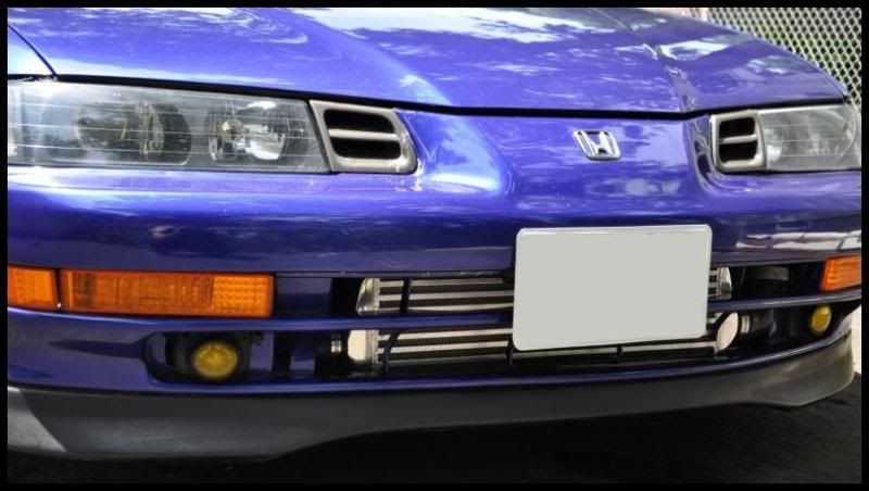
This has been done only by a select few, while others are forced to cut up their bumper and get rid of their fog lights in order to run their IC piping – I wanted something different, and plus I love my JDM amber fogs .. so this idea came to mind during the build.
BTW, I have a half-sized radiator and A/C deleted which gave me the space that I needed to make this work.
These are the parts used in my build and descriptions of where and how each item was used. Pictures help a lot to visualize everything as well .. so here it is ..
Intercooler
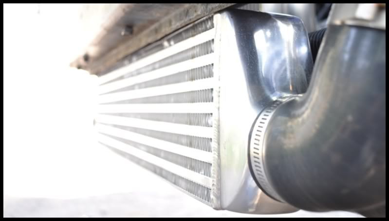
The intercooler is fairly small, but for my power goal its sufficient .. its overall size is 27”x5.5”x2.5” and its core size is 21”x5.5”x2.5”. Bought off of eBay from seller – dnamotoring – for 60-dollars shipped from CA, awesome deal and I recommend this seller and Intercooler to others . It has a total of 6 threaded bungs welded on it for attachment/support , 3 on the top of IC and 3 on the bottom.
The only bad thing about this specific intercooler is that it had 2.0” inlet and outlet, not the usual 2.5” .. that did not bother me for my power goal in mind so I looked into ways that I can transition from my 2.5” diameter pipe down to 2.0” inlet, and same thing on the other side .. more on this in the T-bolt and Coupler section.
Intercooler piping
2.5” diameter aluminum. Bought the piping kit off eBay, it’s a generic kit, just make sure you have at least ( 2 ) 90* bends, ( 2 ) 45* bends, ( 1 ) 180* bend, and ( 2 ) foot straight pipes. Mostly all intercooler kits will give you this.
T-bolts and Clamps
To secure your couplers to your piping. The t-bolts came with my intercooler piping, they were also 2.5”. Now since my intercooler has 2.0” inlet/outlet and my turbo compressor has a 2.0” outlet, these 2.5” t-bolts were not going to work for those sites .. I just went to an auto-parts store and bought your basic clamps that tightened down to 2.0” .. problem solved.
Couplers
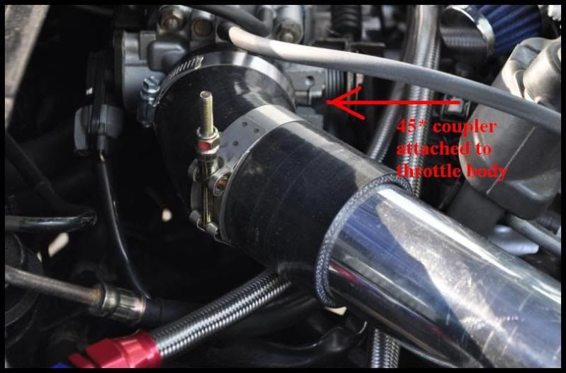
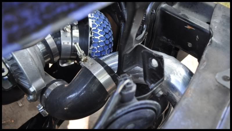
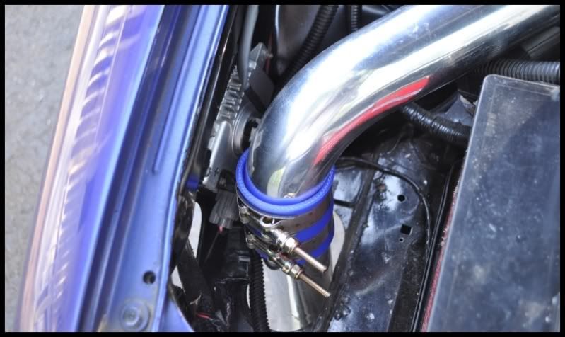
I purchased special black 5-ply silicon couplers that are angled, bought from SiliconeIntakes.com .. My setup contained ( 2 ) 90* bend reducers 2.5” to 2.0”, ( 1 ) 45* bend reducer 2.5” to 2.0”, ( 1 ) 45* bend reducer for my turbo compressor inlet 3.0” to 2.5”, and ( 1 ) 2.5” 45* elbow that went at the throttle body. Totoal for just these silicon couplers was $ 110.00 shipped. There are 2 more straight couplers that came with my intercooler piping kit that I used to join the HKS BOV-flanged pipe to the rest of the system.
Bumper support
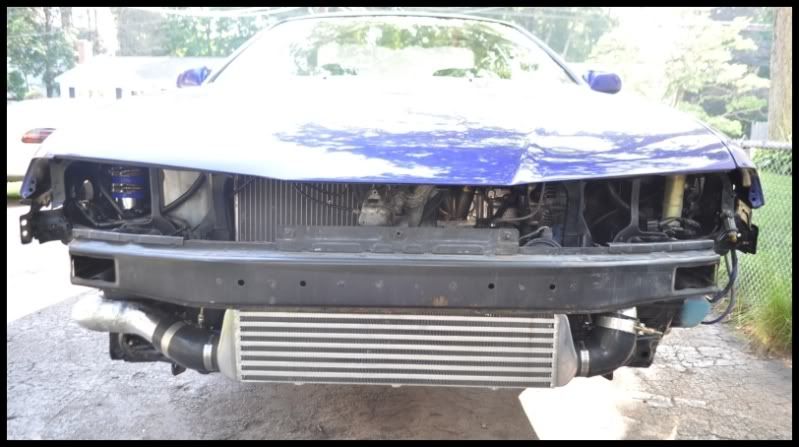
I drilled a hole for a long bolt to go through the top of the bumper support all the way to the bottom, 4 steel layers to drill through, and threaded the bolt right at the center of the IC. Nice and sturdy.
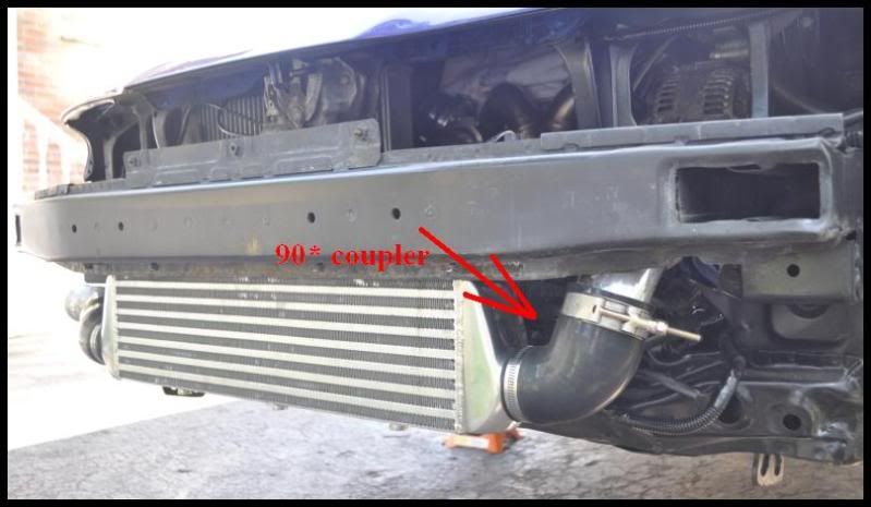
In the pictures you’ll see where exactly I placed my IC in relation to the bumper support, it went right behind the middle support wedge.
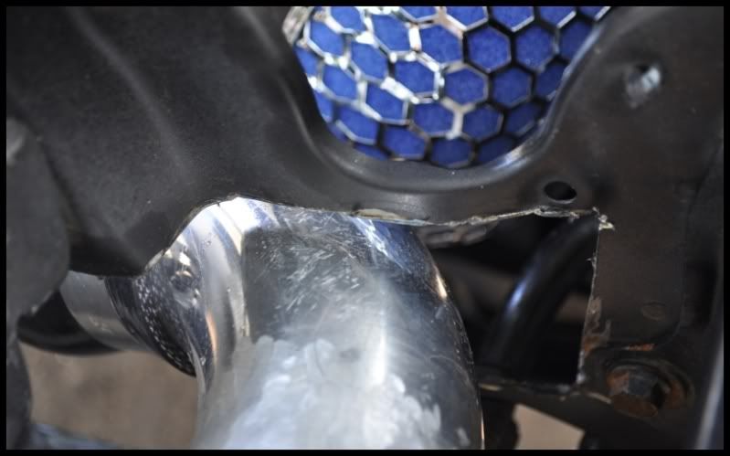
I also cut a section of the bumper support off to route the pre-intercooler piping, you’ll see the exact location in the picture.
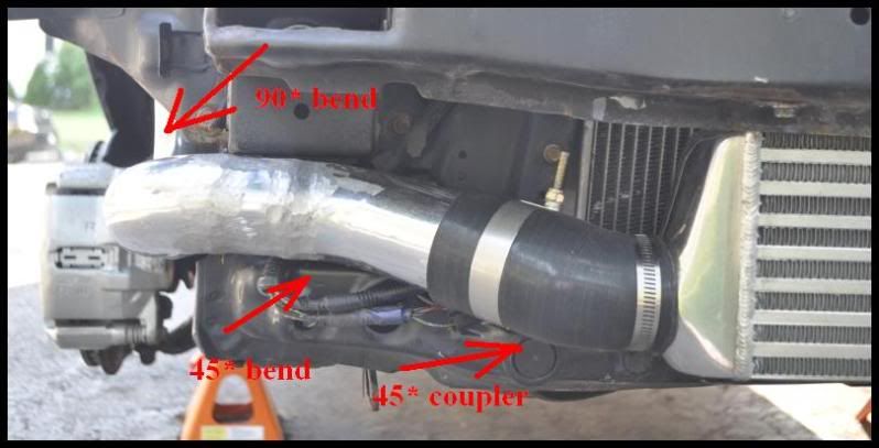
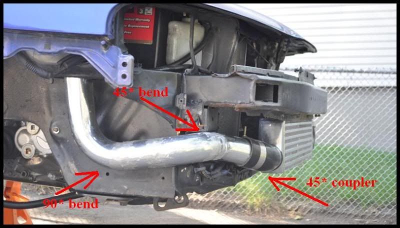
Pipe Bends
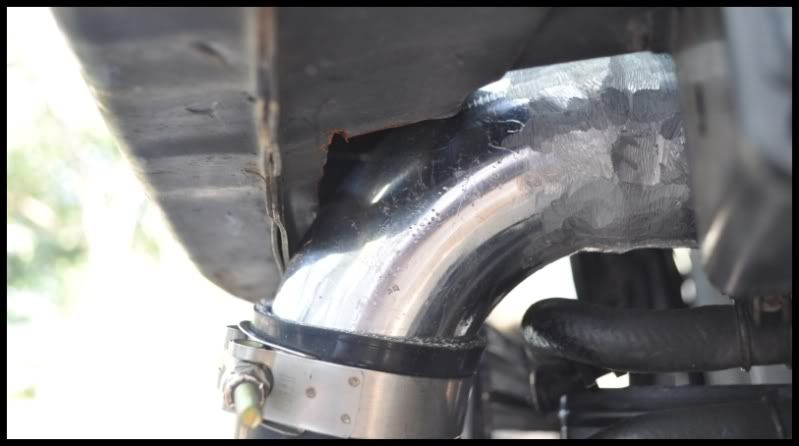
Nothing too crazy here, just measure 3 times and cut once. You should have all the bends come with your purchased kit – so all that’s left for you to do is cut the piping to appropriate lengths and join together. Welds are better than couplers, but some locations are just better to use with couplers. BTW, my welds suck I know, first time welder here, they were so bad that I had to grind them down for a somewhat smoother finish – but with more practice I will get better.
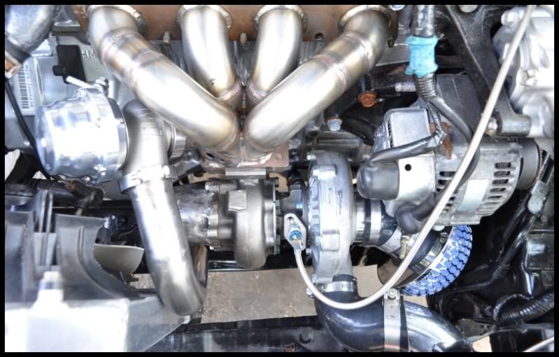
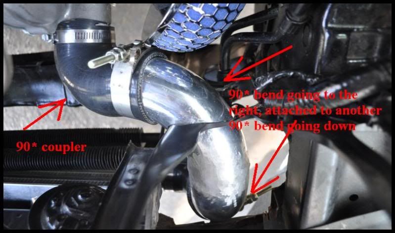
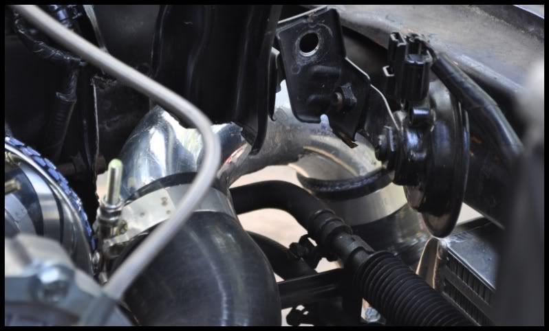
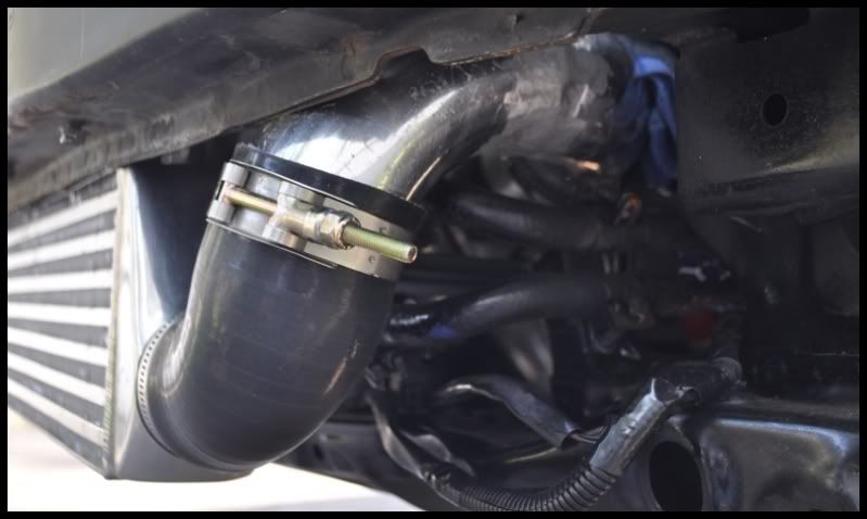
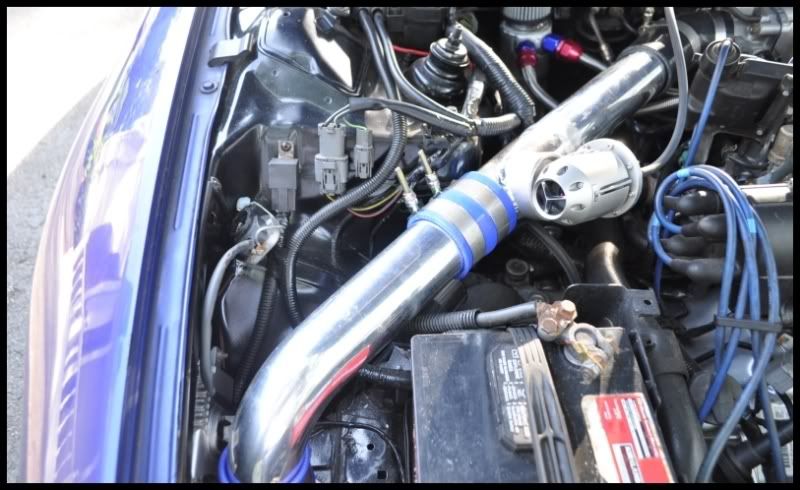
So the passenger IC piping from the IC outlet flows the traditional way into the hole near the battery and from there into the throttle body. The real custom routing comes into play are you take a look into the piping coming off of the turbo compressor outlet and going into the intercooler inlet. I took a picture and wrote on it pretty much what I did. The piping I routed above the power steering cooler, there was already a small hole above it on the radiator support frame, I just cut the hole bigger and removed the metal that was in the way.
Just keep in mind that your turbo and turbo manifold may be different than mine (my setup uses the Spoolin’ Performance Quick4 manifold and a Garrett t3/t04e turbocharger) and in that case your routing on that side will be a little different but immediately off of the intercooler it should be the same.
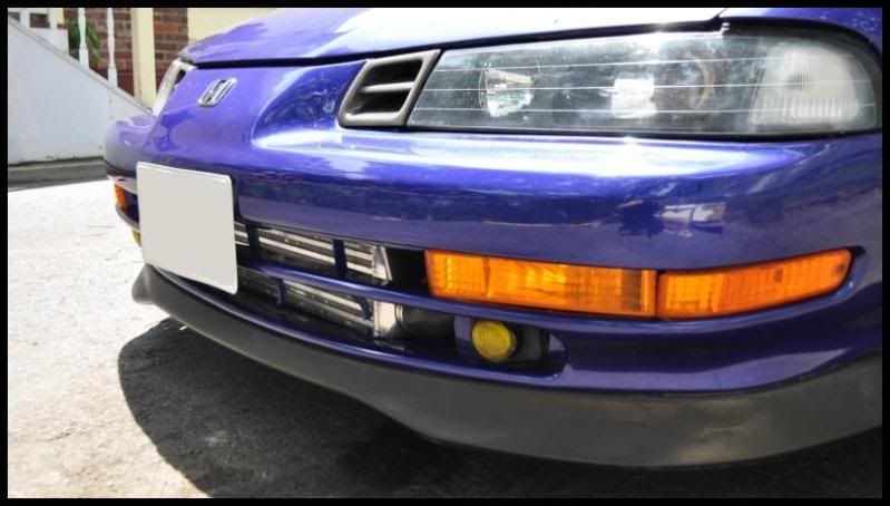
And that is all .. the pictures point to the different reducers and pipes used in this build along with the angles that are best in order for this setup to clear your fog lights .. have fun with best of both worlds.
Pros
.. able to keep your fog lights
.. able to keep your windshield washer fluid reservoir and connections
.. slightly quicker turbo spool up due to the fact that you don’t have extra piping running into the driver’s side wheel-well. This cuts out about 2 feet of piping
.. able to keep your Power Steering cooler in stock location and not mess with moving and mounting it.
.. doing something that few have done, and pulling it off
Cons
.. more time consuming than usual, but if you want something done right it always takes more time
On with the pictures ::
This has been done only by a select few, while others are forced to cut up their bumper and get rid of their fog lights in order to run their IC piping – I wanted something different, and plus I love my JDM amber fogs .. so this idea came to mind during the build.
BTW, I have a half-sized radiator and A/C deleted which gave me the space that I needed to make this work.
These are the parts used in my build and descriptions of where and how each item was used. Pictures help a lot to visualize everything as well .. so here it is ..
Intercooler
The intercooler is fairly small, but for my power goal its sufficient .. its overall size is 27”x5.5”x2.5” and its core size is 21”x5.5”x2.5”. Bought off of eBay from seller – dnamotoring – for 60-dollars shipped from CA, awesome deal and I recommend this seller and Intercooler to others . It has a total of 6 threaded bungs welded on it for attachment/support , 3 on the top of IC and 3 on the bottom.
The only bad thing about this specific intercooler is that it had 2.0” inlet and outlet, not the usual 2.5” .. that did not bother me for my power goal in mind so I looked into ways that I can transition from my 2.5” diameter pipe down to 2.0” inlet, and same thing on the other side .. more on this in the T-bolt and Coupler section.
Intercooler piping
2.5” diameter aluminum. Bought the piping kit off eBay, it’s a generic kit, just make sure you have at least ( 2 ) 90* bends, ( 2 ) 45* bends, ( 1 ) 180* bend, and ( 2 ) foot straight pipes. Mostly all intercooler kits will give you this.
T-bolts and Clamps
To secure your couplers to your piping. The t-bolts came with my intercooler piping, they were also 2.5”. Now since my intercooler has 2.0” inlet/outlet and my turbo compressor has a 2.0” outlet, these 2.5” t-bolts were not going to work for those sites .. I just went to an auto-parts store and bought your basic clamps that tightened down to 2.0” .. problem solved.
Couplers
I purchased special black 5-ply silicon couplers that are angled, bought from SiliconeIntakes.com .. My setup contained ( 2 ) 90* bend reducers 2.5” to 2.0”, ( 1 ) 45* bend reducer 2.5” to 2.0”, ( 1 ) 45* bend reducer for my turbo compressor inlet 3.0” to 2.5”, and ( 1 ) 2.5” 45* elbow that went at the throttle body. Totoal for just these silicon couplers was $ 110.00 shipped. There are 2 more straight couplers that came with my intercooler piping kit that I used to join the HKS BOV-flanged pipe to the rest of the system.
Bumper support
I drilled a hole for a long bolt to go through the top of the bumper support all the way to the bottom, 4 steel layers to drill through, and threaded the bolt right at the center of the IC. Nice and sturdy.
In the pictures you’ll see where exactly I placed my IC in relation to the bumper support, it went right behind the middle support wedge.
I also cut a section of the bumper support off to route the pre-intercooler piping, you’ll see the exact location in the picture.
Pipe Bends
Nothing too crazy here, just measure 3 times and cut once. You should have all the bends come with your purchased kit – so all that’s left for you to do is cut the piping to appropriate lengths and join together. Welds are better than couplers, but some locations are just better to use with couplers. BTW, my welds suck I know, first time welder here, they were so bad that I had to grind them down for a somewhat smoother finish – but with more practice I will get better.
So the passenger IC piping from the IC outlet flows the traditional way into the hole near the battery and from there into the throttle body. The real custom routing comes into play are you take a look into the piping coming off of the turbo compressor outlet and going into the intercooler inlet. I took a picture and wrote on it pretty much what I did. The piping I routed above the power steering cooler, there was already a small hole above it on the radiator support frame, I just cut the hole bigger and removed the metal that was in the way.
Just keep in mind that your turbo and turbo manifold may be different than mine (my setup uses the Spoolin’ Performance Quick4 manifold and a Garrett t3/t04e turbocharger) and in that case your routing on that side will be a little different but immediately off of the intercooler it should be the same.
And that is all .. the pictures point to the different reducers and pipes used in this build along with the angles that are best in order for this setup to clear your fog lights .. have fun with best of both worlds.
Pros
.. able to keep your fog lights
.. able to keep your windshield washer fluid reservoir and connections
.. slightly quicker turbo spool up due to the fact that you don’t have extra piping running into the driver’s side wheel-well. This cuts out about 2 feet of piping
.. able to keep your Power Steering cooler in stock location and not mess with moving and mounting it.
.. doing something that few have done, and pulling it off
Cons
.. more time consuming than usual, but if you want something done right it always takes more time
On with the pictures ::
Last edited by street_ride14; Jun 23, 2010 at 05:43 PM.
Thread Starter
Honda-Tech Member
Joined: Mar 2006
Posts: 1,528
Likes: 2
From: MA
^ yup, thats explained in the text .. I'm a new welder and my welds looked like **** .. so I grinded them down so that they would at least look somewhat better. With experience I will get better at it.


Thread
Thread Starter
Forum
Replies
Last Post