

Vacuum line set up? diagram inside

Thread Starter
Honda-Tech Member
Joined: Apr 2008
Posts: 3,163
Likes: 3
From: Fontana, Ca, United States
ok, so ive done some research on here and i set up the lines as i read.
but even after checking everything, i do not feel much of a vacuum force when
i unplug a vacuum line.
this is how i have it set up
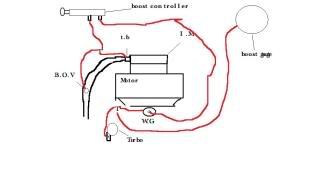
upper connection of W.G is hooked up to a manual boost controller
side connection goes to the turbo housing with a "T" fitting.
other end of "T" fitting goes to the boost gauge.
B.O.V has "T" fitting as well
one goes to B.O.V
one goes to the manual boost controller
and one goes to the T.B
here is a diagram.
the B.O.V is not going off when we rev it up and the W.G doesnt open up.
i do not feel much of a vacuum when i remove a line.
any ideas?
EDIT: sorry for the small picture of the diagram.
i dont know how to make it bigger
but even after checking everything, i do not feel much of a vacuum force when
i unplug a vacuum line.
this is how i have it set up
upper connection of W.G is hooked up to a manual boost controller
side connection goes to the turbo housing with a "T" fitting.
other end of "T" fitting goes to the boost gauge.
B.O.V has "T" fitting as well
one goes to B.O.V
one goes to the manual boost controller
and one goes to the T.B
here is a diagram.
the B.O.V is not going off when we rev it up and the W.G doesnt open up.
i do not feel much of a vacuum when i remove a line.
any ideas?
EDIT: sorry for the small picture of the diagram.
i dont know how to make it bigger
Thread Starter
Honda-Tech Member
Joined: Apr 2008
Posts: 3,163
Likes: 3
From: Fontana, Ca, United States
I was feeling around the piping and silicone cuplings, when my friend revs
the motor, i do feel a leak in the piping near a silicone connection.
will that cause any of the "symptoms" that i described?
the motor, i do feel a leak in the piping near a silicone connection.
will that cause any of the "symptoms" that i described?

Honda-Tech Member
Joined: Feb 2001
Posts: 6,883
Likes: 4
From: CT
you have it set up completely wrong.
your manual boost controller goes between the turbo and the bottom port of the wastegate. the bov and boost gauge go to the IM.
your manual boost controller goes between the turbo and the bottom port of the wastegate. the bov and boost gauge go to the IM.
Honda-Tech Member
Joined: Aug 2007
Posts: 1,110
Likes: 0
From: Pcola, Florida
i have a MBC to, he is correct a line goes from the turbo housing to the MBC, and the second line goes from the MBC to the Wastegate. I use to have a diagram but deleted it . You found the right spot for your research because this is where i first learned how to set my turbo setup up. 
Thread Starter
Honda-Tech Member
Joined: Apr 2008
Posts: 3,163
Likes: 3
From: Fontana, Ca, United States
one heading to the MBC
one to the bottom port of WG
and one to the turbo housing
and the BOV has a "T" as well
one to the BOV
one to the IM
and one to the boost gauge?
is this correct?
Thread Starter
Honda-Tech Member
Joined: Apr 2008
Posts: 3,163
Likes: 3
From: Fontana, Ca, United States

so turbo to MBC port and other MBC port to side port of WG?
and for the BOV:
"T" fitting
one to BOV
one to boost gauge
and one to IM/TB

Trending Topics

Honda-Tech Member
Joined: Aug 2007
Posts: 1,110
Likes: 0
From: Pcola, Florida
For the MBC Check this picture 1 out
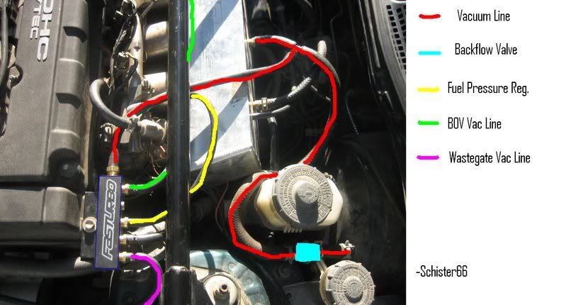
For the Vacuum setup check out pic 2 . You see 3 lines right? The one to the right goes to the FPR Fuel pressure regulator. The T connects the Boost gauge. The center line goes to the cruise i believe i didnt look further into it but ignor that line. The 3rd line to the left goes to the Blow off valve.
Hope this helps.
Honda-Tech Member
Joined: Mar 2006
Posts: 1,153
Likes: 0
You guys do realize it doesn't matter if you put the vac source at the compressor housings or at the intake manifold, right? At the compressor housing it is reading the pressure a TOUCH sooner than at the intake manifold and it is just getting a pressure reference before the IC pressure drop. That's it. As far as function is concerned, it really doesn't matter.
If it requires a pressure/vaccum reading, the source can be the intake manifold. It's as simple as that.
If it requires a pressure/vaccum reading, the source can be the intake manifold. It's as simple as that.

Thread
Thread Starter
Forum
Replies
Last Post
.RTErnie
Welding / Fabrication
48
Feb 24, 2009 04:16 PM
seeeya04
Forced Induction
9
Dec 1, 2005 06:40 AM