

***Porting for Dummies***

Thread Starter
Junior Member
Joined: Jan 2004
Posts: 278
Likes: 0
From: palatine, Il, United states
There are so many posts of DIY cylinder heads, intake manifolds..ETC. I think that its about time that someone created a thread where all of the DIY porters can go to share/gain knowledge. After all, aside from all the arguing, hating, complaining, ETC, this site is here to help one another. Now this thread may have some haters, it will also be filled with plenty of valuable information that will help us that don't have pockets deep enough to pay someone to do it. Or just plain and simple you get much more satisfaction when you do it yourself. Many will argue to leave it to the 'pros' or you can do anything without a flow bench...ETC. So please leave all of the negativity out and lets get this thing rolling. Things that should be discussed,
*Cleaning
*Shaping
*Porting
*Bowl area
*Valve guide Length
*Throat size
*Valve size
*Port size Related to engine size
*Runner length
*Porting tools
*Tips/ Tricks/ Things that have worked for you
Please post pics of your DIY headwork/intake manifold work. As much or as little as you know, please post any info you have. I know there are plenty of "hows my port work' and 'DIY port job' Threads, but people just hate and hate, why not put them all in one place and make it easy.
ENJOY
Thread Starter
Junior Member
Joined: Jan 2004
Posts: 278
Likes: 0
From: palatine, Il, United states
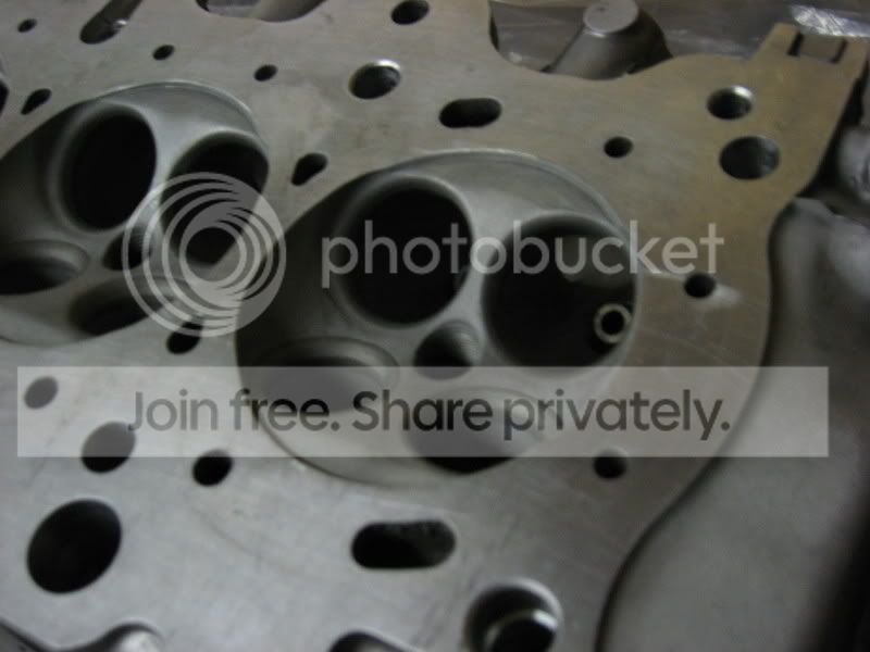
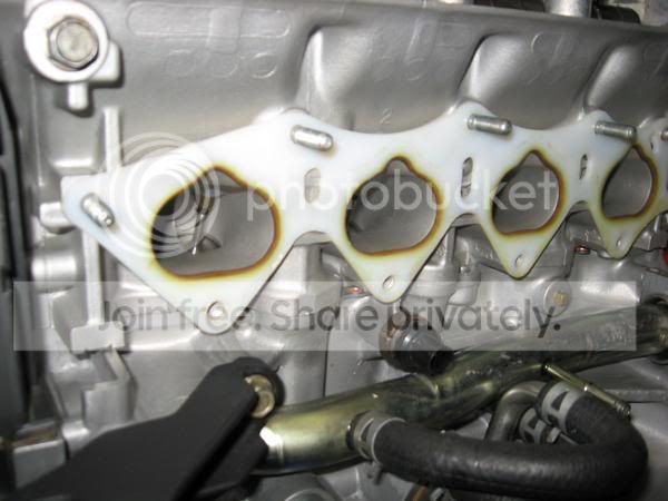
Her are pics of my B series head I did about a year and a half ago. Ports are huge, bowls are smoothed/blended, over all it came out pretty good for never doing it before. I will be doing another one very soon. Critque, I know there are many things I would do different.
Honda-Tech Member
Joined: Feb 2004
Posts: 1,036
Likes: 0
From: T Dot
<TABLE WIDTH="90%" CELLSPACING=0 CELLPADDING=0 ALIGN=CENTER><TR><TD>Quote, originally posted by JDM1civic »</TD></TR><TR><TD CLASS="quote">Ports are huge</TD></TR></TABLE>
it all went out the window with those 3 words. this thread has the perfect title
it all went out the window with those 3 words. this thread has the perfect title
Thread Starter
Junior Member
Joined: Jan 2004
Posts: 278
Likes: 0
From: palatine, Il, United states
you are just one of the many inconsiderate people on here with your head stuck way to far up your @ss. I kno the ports are huge, it was my first attempe at porting. Its people like you that try to discourage everyone from trying something new. The thread is made to inform/educate people. Critquing is fine, hating is a different story.
Honda-Tech Member
Joined: Nov 2003
Posts: 1,755
Likes: 2
From: Alberta, Canada
<TABLE WIDTH="90%" CELLSPACING=0 CELLPADDING=0 ALIGN=CENTER><TR><TD>Quote, originally posted by Rollo Lawson »</TD></TR><TR><TD CLASS="quote">
it all went out the window with those 3 words. this thread has the perfect title
</TD></TR></TABLE>
I take it you are a competent porter with a flowbench in your garage *rollseyes*
I have spare cylinder heads laying around my basement and you had better believe i'll hog the ports out of one of them for ***** and giggles to see how it does on the butt dyno one day.
GTFO of this thread with your pompous attitude.
Honda-Tech Member
Joined: Oct 2004
Posts: 1,073
Likes: 1
From: Mid East Deserts
came accross this thread not long time ago. lots of good info 
https://honda-tech.com/zerothread?id=400842
https://honda-tech.com/zerothread?id=400842
Member
Joined: May 2003
Posts: 1,609
Likes: 1
Wow you need to take a deep breath and relax.
You asked for opinions on an open forum,if you only wanted to hear how great everything you ever did was go talk to your mother,lol.
Seriously now,the pics don't tell us anything really,and in most cases they never do even if they were close-ups and clear.
I don't care if someone wants to learn or experiment on their own heads if they want to,go for it,like Rocky did,lol.
You just need to understand and I'm not trying to insult you here.Porting is a science/art not a mechanical operation where you just make things bigger and wha-la the car goes faster.
If someone paints their car in the driveway with spray paint cans,yes the cars painted,but it's not the same is it.
It's my opinion and experience that home porters just ruin their heads and then ask me/other professionals to fix them and then don't understand why in most cases the heads are beyond fixing when you factor in the cost/time required to make them right again.
You should learn these things on destroyed heads so you don't waste your money and lessen the supply of heads they don't make anymore.
But that's just how I feel,like I said it's your head to do with as you see fit.
Modified by Fkned at 3:37 PM 9/20/2008
Trending Topics
Member
Joined: May 2003
Posts: 1,609
Likes: 1
I will tell you the most important thing in cylinder heads.
The air has to go past the valve that is the limiting factor.
No matter how big you make the rest of the port it will almost always be the valve that limits airflow.You will just be slowing the air down by making the volume bigger then needed.
The air has to go past the valve that is the limiting factor.
No matter how big you make the rest of the port it will almost always be the valve that limits airflow.You will just be slowing the air down by making the volume bigger then needed.


Here's some info from the thread posted by ef92b.
I'm brand-new to this forum (used to be on JDMcivic.com) but hopefully I can become a consistent contributor. I'm bored tonight, so I figured I write up a little basic head porting article. Power is in the heads, and if you're on a budget you can free up as much as 20 hp just from porting and polishing. Obviously there are more "sophisticated" ways of doing this....but double digit horsepower for the cost of common shop tools? It sounds good to me. And also it doesn't take a brain scientist to port heads. The #1 most important thing is attention to detail. Oh yea, and a little bit of time on your hands...so here we go, I'm not garunteeing (sp?) perfection! hehe
-------------------------------------------------------------------------------------------------
One of the most important rules of high performance building is to remember that the horsepower is in the heads. The total investment in the cylinder heads of a high performance engine can represent a significant portion of the entire engine budget, and in the search for horsepower, you can't go wrong ordering a set of heads from one of the cylinder head gurus. But what if your budget is not within the "guru" price range? Noticeable gains can still be made by the do-it-yourselfer through careful portwork and attention to detail. Follow along as I walk you through the basics of head porting.
This is a description of basic porting techniques used to port a stock Honda/Acura casting. These include the B-series, D-series, and H-series, with either stock or aftermarket valves. Heads with larger valves should have much more porting work done in order to flow to their full potential. I am not a professional. The head porter's trade is truly one of a Black Art form. Don't expect your heads to flow as well as a professional's would.
I like to use a rotary file of different shapes (ball, acorn, and tulip shape). For finishing, I use a sanding roll and small flap wheels (80grit). These are all available to fit a Dremel Moto tool, available at any well-equipped hobby or hardware store. To keep things the identical, I like to do one step at a time to all 4 ports before moving on to the next step. This process usually takes approximately 10-20 hrs. to complete.
Valves and Seats
The use of stainless steel valves will always improve flow over standard stock valves, as they have a much tighter radius on the backside, allowing for less obstruction at the opening when the valves are open at low lifts. A good 3-4-5-angle valve job will enhance the flow improvement even more. You can pay a professional to do this work. I have access to some really nice grinding stones at work and have good success grinding the valve angles by hand, with the exception of the sealing 45 degree angle. I leave that one alone.
Port and Chamber Area Around the Seat
The valve seats are steel inserts pressed into the aluminum casting. There is usually a mismatch of metal in the port and in the combustion chamber. Take time to blend the port and chamber until the step (mismatch) is gone, using your finger to feel for imperfections. When working around the valve seat, take extreme care not to accidentally nick the 45 degree angle in the set, or you will be taking the head to the machine shop for dressing the seat. If the heads are used, the do the port work first.
Combustion Chambers
Too much deck height is a bad thing, resulting in loss of turbulence at TDC when the mixture is ignited and reduce combustion efficiency. Deep combustion chambers are another problem, as they tend to shroud the valves giving very little room for flow around the valve into the chamber. I like to lay back both the plug side and non-plug side of the chamber by widening the angles. I also unshroud the valves by opening the sides of the chamber up to the cylinder bore diameter. I then blend all this together, smoothing all imperfections and casting marks. This means that the chamber is opened up all the way around, making for a much clearer entry for gasses into the cylinder (and exit for the exhaust). I then flycut the heads to get the desired chamber CC's (with .050" - .070" deck height). I then use a flapwheel to remove the sharp edge all the way around. Take care not to round the sides where the cylinder will seal against the head. It is a good idea to scribe a line around the head where the cyl will meet the head, and to drop some junk valves into the heads to protect the valve seats while working in the chambers.
The goal is to provide the best port-match for the specific valve. "Hogging it out" is not the goal. The stock size port does not need to be enlarged very much to get good results, and too big of a port will cause a loss of port velocity and create unwanted turbulence. The goal is to reduce the restriction of the port.
Set the head in front of you with the intake flange facing you (right side up). The ports are round, and we are going to make them oval in the direction of the sparkplug holes, similar to a "V" shape. If you have a intake gasket or pattern to borrow, now is the time to draw/scribe it out onto the intake flange. Hold the grinder perpendicular to the flange and open up the ports to the new port shape. Don't worry about blending into the port yet. Take your time and make all the port openings look the same.
Set the acorn file out as far as you can in the grinder to give maximum reach into the port. On most heads the port has a casting part line right above the intake guide boss. This part line makes for a major corner right above the guide boss blocking any flow trying to go over top of the guide. You will want to blend this corner away by plunging the grinder down through the port going over top of the guide boss. Once through, work from the chamber side of the port to blend the contour. There is a fair amount of metal to remove here so take your time and study the port closely. The goal is to make the port above the guide look like it does below the guide, in effect straightening the port. This will open up a new flow path for intake charge. I also like to thin the intake guide boss, as it does very little anyway. Shape the metal into a nice teardrop shape around the guide, working from both ends of the port.
Once the major porting has been performed, blend the whole port together, removing all the bumps and corners, radiusing the port into the new openings. Use your finger to feel for irregularities. The contour should be one nice smooth blend all the way to the valve seat. Work slowly!
Exhaust Ports
I pretty much go by the book here. Without removing too much guide boss material, I like to contour the boss much in the same way that we did the intake bosses. Because the boss takes up so much of the port in that area, it helps flow to widen (or squeeze) the port around the boss. Working from the seat side of the port, start widening the port on either side of the boss just below the seat. You can blend these wide pockets into the port from the exit flange side. There is a sharp edge on most heads on the inside radius of the port, and it is almost impossible to see (you have to use your finger to find it). Tighten-up the inside radius, leading away from the seat, blending this edge away. Do not take too much material away here or there will not be enough left to support the seat properly. Lastly, open up the port at the header flange. Use an appropriate size exhaust gasket for this pattern.
Finishing Up
I like using a flapwheel wherever I can, as they do a great job of smoothing out the bumps and blending everything (and they last a long time). If the flapwheel will not smooth it out, go back to the rotary file. If you have done it right, you will have a professional looking port job. With any luck you will have one that flows almost as good as a professional port job as well.
Match-Porting
To take full benefit of your efforts it is important to match-port the intake manifolds. I use the same pattern gasket and transfer the port shape to the manifold base.
Good luck and remember, this is free personal advice.
Originally Posted by BurlyHatch
I'm brand-new to this forum (used to be on JDMcivic.com) but hopefully I can become a consistent contributor. I'm bored tonight, so I figured I write up a little basic head porting article. Power is in the heads, and if you're on a budget you can free up as much as 20 hp just from porting and polishing. Obviously there are more "sophisticated" ways of doing this....but double digit horsepower for the cost of common shop tools? It sounds good to me. And also it doesn't take a brain scientist to port heads. The #1 most important thing is attention to detail. Oh yea, and a little bit of time on your hands...so here we go, I'm not garunteeing (sp?) perfection! hehe
-------------------------------------------------------------------------------------------------
One of the most important rules of high performance building is to remember that the horsepower is in the heads. The total investment in the cylinder heads of a high performance engine can represent a significant portion of the entire engine budget, and in the search for horsepower, you can't go wrong ordering a set of heads from one of the cylinder head gurus. But what if your budget is not within the "guru" price range? Noticeable gains can still be made by the do-it-yourselfer through careful portwork and attention to detail. Follow along as I walk you through the basics of head porting.
This is a description of basic porting techniques used to port a stock Honda/Acura casting. These include the B-series, D-series, and H-series, with either stock or aftermarket valves. Heads with larger valves should have much more porting work done in order to flow to their full potential. I am not a professional. The head porter's trade is truly one of a Black Art form. Don't expect your heads to flow as well as a professional's would.
I like to use a rotary file of different shapes (ball, acorn, and tulip shape). For finishing, I use a sanding roll and small flap wheels (80grit). These are all available to fit a Dremel Moto tool, available at any well-equipped hobby or hardware store. To keep things the identical, I like to do one step at a time to all 4 ports before moving on to the next step. This process usually takes approximately 10-20 hrs. to complete.
Valves and Seats
The use of stainless steel valves will always improve flow over standard stock valves, as they have a much tighter radius on the backside, allowing for less obstruction at the opening when the valves are open at low lifts. A good 3-4-5-angle valve job will enhance the flow improvement even more. You can pay a professional to do this work. I have access to some really nice grinding stones at work and have good success grinding the valve angles by hand, with the exception of the sealing 45 degree angle. I leave that one alone.
Port and Chamber Area Around the Seat
The valve seats are steel inserts pressed into the aluminum casting. There is usually a mismatch of metal in the port and in the combustion chamber. Take time to blend the port and chamber until the step (mismatch) is gone, using your finger to feel for imperfections. When working around the valve seat, take extreme care not to accidentally nick the 45 degree angle in the set, or you will be taking the head to the machine shop for dressing the seat. If the heads are used, the do the port work first.
Combustion Chambers
Too much deck height is a bad thing, resulting in loss of turbulence at TDC when the mixture is ignited and reduce combustion efficiency. Deep combustion chambers are another problem, as they tend to shroud the valves giving very little room for flow around the valve into the chamber. I like to lay back both the plug side and non-plug side of the chamber by widening the angles. I also unshroud the valves by opening the sides of the chamber up to the cylinder bore diameter. I then blend all this together, smoothing all imperfections and casting marks. This means that the chamber is opened up all the way around, making for a much clearer entry for gasses into the cylinder (and exit for the exhaust). I then flycut the heads to get the desired chamber CC's (with .050" - .070" deck height). I then use a flapwheel to remove the sharp edge all the way around. Take care not to round the sides where the cylinder will seal against the head. It is a good idea to scribe a line around the head where the cyl will meet the head, and to drop some junk valves into the heads to protect the valve seats while working in the chambers.
The goal is to provide the best port-match for the specific valve. "Hogging it out" is not the goal. The stock size port does not need to be enlarged very much to get good results, and too big of a port will cause a loss of port velocity and create unwanted turbulence. The goal is to reduce the restriction of the port.
Set the head in front of you with the intake flange facing you (right side up). The ports are round, and we are going to make them oval in the direction of the sparkplug holes, similar to a "V" shape. If you have a intake gasket or pattern to borrow, now is the time to draw/scribe it out onto the intake flange. Hold the grinder perpendicular to the flange and open up the ports to the new port shape. Don't worry about blending into the port yet. Take your time and make all the port openings look the same.
Set the acorn file out as far as you can in the grinder to give maximum reach into the port. On most heads the port has a casting part line right above the intake guide boss. This part line makes for a major corner right above the guide boss blocking any flow trying to go over top of the guide. You will want to blend this corner away by plunging the grinder down through the port going over top of the guide boss. Once through, work from the chamber side of the port to blend the contour. There is a fair amount of metal to remove here so take your time and study the port closely. The goal is to make the port above the guide look like it does below the guide, in effect straightening the port. This will open up a new flow path for intake charge. I also like to thin the intake guide boss, as it does very little anyway. Shape the metal into a nice teardrop shape around the guide, working from both ends of the port.
Once the major porting has been performed, blend the whole port together, removing all the bumps and corners, radiusing the port into the new openings. Use your finger to feel for irregularities. The contour should be one nice smooth blend all the way to the valve seat. Work slowly!
Exhaust Ports
I pretty much go by the book here. Without removing too much guide boss material, I like to contour the boss much in the same way that we did the intake bosses. Because the boss takes up so much of the port in that area, it helps flow to widen (or squeeze) the port around the boss. Working from the seat side of the port, start widening the port on either side of the boss just below the seat. You can blend these wide pockets into the port from the exit flange side. There is a sharp edge on most heads on the inside radius of the port, and it is almost impossible to see (you have to use your finger to find it). Tighten-up the inside radius, leading away from the seat, blending this edge away. Do not take too much material away here or there will not be enough left to support the seat properly. Lastly, open up the port at the header flange. Use an appropriate size exhaust gasket for this pattern.
Finishing Up
I like using a flapwheel wherever I can, as they do a great job of smoothing out the bumps and blending everything (and they last a long time). If the flapwheel will not smooth it out, go back to the rotary file. If you have done it right, you will have a professional looking port job. With any luck you will have one that flows almost as good as a professional port job as well.
Match-Porting
To take full benefit of your efforts it is important to match-port the intake manifolds. I use the same pattern gasket and transfer the port shape to the manifold base.
Good luck and remember, this is free personal advice.
Originally Posted by HEAD
I don't know if you grind everyday but you certainly explained it well. I hope you don't mind but I would like to say that I perfer using a cartrige roll over a flapper wheel 60 grit on intake 120 on the exhaust mostly for time concerns it takes way to long to sand a port out with a flapper(my opinion not fact)and to me it's also real hard to get out all the grinding marks using the flapper but I think it also really depends how much patience you have for such a thing. As far as grinding around the seat if you get some junk valves with the same head diameter and take them to a machine shop have them cut the 45 angle till there is no margin and the valve is almost razor sharp it will cover the seat and you can blend the valve job in alot nicer.
As far as sanding the intake side I have never seen more than a couple of cfm from doing it I think it does help using the flap wheel over the short turn because most of the time using a cartrige roll in this area will leave a point at the top of the turn and I would also like to see this done to blend the valve job in, but I have never seen it hurt flow or performance by sanding the port, I would say if you went crazy on polishing and mirror polished it that would hurt atomization causing the fuel to puddle or fall out of suspention . but that's just my opinion.
oh I almost forgot to say for another porting tip would be if you are grinding with an aluminum bit go back over it with a cast iron bit slowly when I say this I mean slow the speed of the grinder down and push a little harder this will make it either A. a smoother finish than the aluminum bit gave(it's actually preety close to polishing it) or..
B. will make it easier for you to polish
Good Luck to those that try!And thanks for the good thread I enjoyed reading it!
that was some good info. i always wanted to port a blown head just for ***** and giggles..... power wise ill leave it to the pros
Honda-Tech Member
Joined: May 2003
Posts: 1,328
Likes: 0
From: r4, mars
<TABLE WIDTH="90%" CELLSPACING=0 CELLPADDING=0 ALIGN=CENTER><TR><TD>Quote, originally posted by Fkned »</TD></TR><TR><TD CLASS="quote">I will tell you the most important thing in cylinder heads.
The air has to go past the valve that is the limiting factor.
No matter how big you make the rest of the port it will almost always be the valve that limits airflow.You will just be slowing the air down by making the volume bigger then needed.</TD></TR></TABLE>
good stuff!
maybe thats why, he last .5" of the ports (pre valve) aka throat
and valve angles (valvejob) are rather one of the most important things done to the head..
i think i read sumwer of a diY ported head, flowed etc and compared to a stock head with one of brad's / RLZ valvejob on stock ports, making more than the ported head...

Joined: Sep 2008
Posts: 21
Likes: 0
From: Portsmouth, VA, 23704
I'll add my .02 into this discussion.
The most critical part of the port job will always be the valve seat and bowl area. As someone pointed out, it's all about what can flow around the valve. Not specifically these motors, but another manufacturer's motors, you can pull the valves out, and it flows the same, right off the showroom floor. Granted, it doesn't have as much flow as a B-series, or especially a K, but do you think that's efficient enough? That's just food for thought.
Here, everyone is talking about what to port.
If I were planning a head for a job, the first thing I'd do is get an Intake Manifold Gasket. In this case, I'd use a Hondata gasket. I'd lay it out on the head, and trace it. I would then port the head to match the gasket. From there, you attempt to smoothly taper the runners going in. This does 2 things - First, you just increased the amount of taper to the bowl area - That increases the velocity of the air as it approaches the bowl, and if the quality is maintained in the bowl area, that will also increase the velocity with which the air flows into the cylinder. It also gives you an oppourtunity to provide a reversion step in the intake manifold. Yes, I've seen some discussion on this above. There is overlap in the valves, this means that some of that hot exhaust air is going to try to back up into the intake. While that may be good for economy, hot, turbulent intake air is definitely bad for power, and if you can stop most of it at the gasket area, and keep cool, fresh air coming in with velocity, you'll make more power.
You would then want to concentrate on the bowl area of the intake ports. Remember, the long side maintains laminar flow fairly well. It's the tight radius bend that tends to make the air turbulent. You can do a couple of things to help that. First, cut away some of the bend. That one is somewhat simple. You can also go down into the corners on either side of the inside bend, and square it up a bit, remove some material, to generate a wider area for that air to flow over, giving it more opportunity to slow down through that section, and it should maintain laminar flow better. What I haven't heard anyone mention, is building up material in the port, as opposed to hogging it out. There are areas on a B-series head, that it would be more beneficial to add material, than remove all that is around it, trying to fix the problem...... Food for thought....
From there, the bowl area should progress down in size, from the ultimate size at the intake, to the smallest point, just before the valve job bottom cut. The depth of that cut actually determines the RPM range in which the motor will perform best. you should of course make sure it's blended smoothly with the bottom cut, which leads to the fact the bottom cut needs more angle than one might think, but probably not the factory 60 degrees, especially on a motor trying to turn the RPM's many of us do with a Honda....
At that point, you'll want to be sure the valve seat is as close to the edge of the valve as your machine shop would dare, with the minimal thickness they would recommend for the seat. Thinner seats actually seal better, and flow better. However, they also have problems with burn-through, if they're too thin...
Exhaust side would be similar, but you wouldn't want to open up the port at the gasket. You'd want to open up the header flange....You may not want to use epoxy in the exhaust side as a filler, but actually build it up with aluminum if needed. Few minor differences, but the rest still applies.....
Joined: Sep 2008
Posts: 21
Likes: 0
From: Portsmouth, VA, 23704
Food for thought for the rough-surface guys.
Ceramic coatings provide an almost ideal texture to promote boundary layer air, as well as preventing heat from the head getting to the intake air, or exhaust heat getting to the head....
Let's not forget you can coat the chambers as well, to prevent heat from soaking into the head as easily, and provide more complete combustion, with less chance of knock/misfire/etc., as the exhaust air will stay hotter, move out faster, create better scavenging, etc..... Simply put, I'm a firm believer in Ceramic coatings in an engine, and they aren't that expensive for the benefits....
Member
Joined: May 2003
Posts: 1,609
Likes: 1
<TABLE WIDTH="90%" CELLSPACING=0 CELLPADDING=0 ALIGN=CENTER><TR><TD>Quote, originally posted by OneSlow92EGSi »</TD></TR><TR><TD CLASS="quote">
It also gives you an oppourtunity to provide a reversion step in the intake manifold. Yes, I've seen some discussion on this above. There is overlap in the valves, this means that some of that hot exhaust air is going to try to back up into the intake. While that may be good for economy, hot, turbulent intake air is definitely bad for power, and if you can stop most of it at the gasket area, and keep cool, fresh air coming in with velocity, you'll make more power.
</TD></TR></TABLE>I think you have a few things mixed up there.
For instance if you have a reversion problem a step at the int manifold/head mating surface isn't going to solve or help that problem,it's already diluted the int charge when it got past the valves into the bowls.Stopping it at the int manifold isn't going to do anything besides stoping it from burping thru the TB.
That hot air your talking about is the EGR system I think you mean.That's what makes for better drivability by keeping the incoming int charge warm in the winter/cold weather climates so the fuel doesn't drop out and stays suppended better.The car will actually have more power without the EGR if it's not needed since the intake charge isn't diluted/heated from the it.That's why we usually block it on race cars.
Joined: Sep 2008
Posts: 21
Likes: 0
From: Portsmouth, VA, 23704
I think you mis-understood.
The step helps cut down on turbulence. You're not going to fix the hot air problem, but you can help the turbulence. That ensures a more complete filling, with the cooler air from the intake, so in effect, it should have that benefit as well.
I was making a generalization about economy. Sure, factory uses EGR to do it. They've also been known to build water jackets into the intakes on some manufacturers cars, in order to pre-heat the air even more......
But again, you will have reversion problems, as well as scavenging, and it's just as key to have that step in the intake, as it is in the head on the exhaust side, IMO...
That's my opinion.
Honda-Tech Member
Joined: Feb 2004
Posts: 815
Likes: 0
From: CA
<TABLE WIDTH="90%" CELLSPACING=0 CELLPADDING=0 ALIGN=CENTER><TR><TD>Quote, originally posted by OneSlow92EGSi »</TD></TR><TR><TD CLASS="quote">I think you mis-understood.
The step helps cut down on turbulence. </TD></TR></TABLE>
Uhhh, no it doesn't. Don't spew wrong information for others to pass on please.
The step helps cut down on turbulence. </TD></TR></TABLE>
Uhhh, no it doesn't. Don't spew wrong information for others to pass on please.

Member
Joined: May 2002
Posts: 5,197
Likes: 1
From: Atl. Beach, fl, duval
If you are going to port your own heads, spend $75.00 on a Superflow Flowbench Operators manual. It has most of the formulas and basic info you need. Lots of diagrams and charts.
Honda-Tech Member
Joined: Feb 2004
Posts: 815
Likes: 0
From: CA
Equal length walls and port roof and floor would help keep the flow laminar. Having a "step" would cause a small area after the step to "roll" at the boundary. The "step" if big enough can cause turbulence. The air in the middle could ride over it but it does in no way cause the flow to be laminar or reduce turbulence.
Joined: Sep 2008
Posts: 21
Likes: 0
From: Portsmouth, VA, 23704
Nobody said to leave a huge area. It should be a small step, and the intake exit should be slightly smaller than the port entrance. It also allows for the mis-alignment of installing the part, as unless you're using some mighty fancy technology, you could create a step on entry, which would seriously be BAD for flow.....
Again, it's my opinion, take it or leave it.
Again, it's my opinion, take it or leave it.
Member
Joined: May 2003
Posts: 1,609
Likes: 1
<TABLE WIDTH="90%" CELLSPACING=0 CELLPADDING=0 ALIGN=CENTER><TR><TD>Quote, originally posted by OneSlow92EGSi »</TD></TR><TR><TD CLASS="quote">I think you mis-understood.
The step helps cut down on turbulence. You're not going to fix the hot air problem, but you can help the turbulence. That ensures a more complete filling, with the cooler air from the intake, so in effect, it should have that benefit as well.
I was making a generalization about economy. Sure, factory uses EGR to do it. They've also been known to build water jackets into the intakes on some manufacturers cars, in order to pre-heat the air even more......
But again, you will have reversion problems, as well as scavenging, and it's just as key to have that step in the intake, as it is in the head on the exhaust side, IMO...
That's my opinion.</TD></TR></TABLE>NO I don't think I misunderstood what you said.Maybe you don't understand how to explain what you mean,because your wrong on both counts.
We make the manifold exit that mates with the head intake port slightly smaller for reasons that have nothing to do with what your saying.
The reason the manifold exit is smaller or exactly the same as the heads int entrance is so that the incomming air doesn't hit the edge of the int port entrance and shear the air making the int entrance seems smaller then it really is.It's the same reason we use a radius on the flow bench when testing the ports.If there is any trublence in the manifold port a step at the mating surface isn't going to stop it at all.
The reason we have a reversion step on the exh port is because the exh gasses that are at the very edge of the port/header walls is cooler then the center and it tries to back up into the port again on overlap because it doesn't have as much inertia as the center of the flow which is the fastest.That's also why we have header wraps to try to keep the header walls from pulling heat out of the exh by radiation.
Modified by Fkned at 1:43 PM 9/21/2008
Honda-Tech Member
Joined: Feb 2004
Posts: 815
Likes: 0
From: CA
Ok, don't learn fluid dynamics off of Honda-Tech. Go buy some books about it. If you have the math down you can easily learn this stuff. A lot of it is conceptual at first which will require some critical thinking. I agree with having the runner exit exact or slightly smaller than the port entrance but it dose not cause laminar flow. Good luck.
Member
Joined: May 2003
Posts: 1,609
Likes: 1
<TABLE WIDTH="90%" CELLSPACING=0 CELLPADDING=0 ALIGN=CENTER><TR><TD>Quote, originally posted by OneSlow92EGSi »</TD></TR><TR><TD CLASS="quote">This is where I learned a LOT of what I know....
</TD></TR></TABLE>This is exactly what I mean by "leave it to the pros".You wouldn't have your car fixed by someone who only learned everything he knows by reading online forums would you?
</TD></TR></TABLE>This is exactly what I mean by "leave it to the pros".You wouldn't have your car fixed by someone who only learned everything he knows by reading online forums would you?