

How can I copy this flange accurately?


Honda-Tech Member
Joined: Sep 2003
Posts: 3,166
Likes: 0
From: Boost is good
Use clay? and cover it up? Then pour plaster into the clay? Let it dry up. Peel away clay. Then you have somewhat of a copy flange? -=P In Plaster!
Measure away from there? Thats how I would imagine it.
Not sure how anyone else would do it. I might be old school. lol.
Measure away from there? Thats how I would imagine it.
Not sure how anyone else would do it. I might be old school. lol.
Couldnt you just trace it with gasket maker.I would imagine after you make the gasket that someone on here can make you a flange from it?
Junior Member
Joined: Nov 2004
Posts: 158
Likes: 0
From: phoenix, az, usa
take a piece of plain printer paper lay it on the piece and use the side of a pencil to rub over the flange the edge's of the flange and bolt holes will come out darker than the rest, its difficult to do it this way because you have to make sure not to move the paper while doing it, but it can be done. i have had to do this a few times to make flanges from a manifold that had already been welded together. Hope this helps maybe somebody else might have a better suggestion.
Junior Member
Joined: Nov 2004
Posts: 158
Likes: 0
From: phoenix, az, usa
or you can use the straight edges of the block (ie the back of the block and oil pan flange) to take measurements to the center of the bolt holes and make it that way becuase it seems only the bolt holes would be the most critical dimensions .
OG Fabricator
Joined: Feb 2005
Posts: 1,864
Likes: 1
From: Burlington, Ont., Canada
if you have a vernier, it isn't hard to do.
1. measure the diameter of the holes
2. measure the shortest tangent distance between any of the two holes, add the diameter and that is the distance between centers.
3. draw a line exactly that length.
4. repeat step 2 from each of the two holes you just measured to the 3rd hole and create an arc from the ends of the line you drew earlier. where the arcs intersect is the point for the third hole center point.
done.
Honda-Tech Member
Joined: Sep 2003
Posts: 278
Likes: 0
From: Cleveland, OH
Get a nice thick piece of posterboard or some other decent thick piece of paper.
Coat the area you want with loctite. Only will take a few drops, then smear the rest with your finger. Use it lightly or else you'll get excess on your gasket/flange template.
Push the paper against the loctite covered surface. Hold for a few seconds.
Pull it off, step back, admire your work.
Coat the area you want with loctite. Only will take a few drops, then smear the rest with your finger. Use it lightly or else you'll get excess on your gasket/flange template.
Push the paper against the loctite covered surface. Hold for a few seconds.
Pull it off, step back, admire your work.
Trending Topics
I'm really 2slow


Joined: Jan 2004
Posts: 8,987
Likes: 7
From: near Laguna Seca CA, USA
get a white piece of paper and place it over. with your fingers oily rub around the edges. cut through the paper with a blade. transter template to a soft metal or even a small piece of wood. cut soft metal/wood for testing. once you know it fits use the wood/soft metal as a template. make your flange out of the desired metal with your tools. 
Honda-Tech Member
Joined: Apr 2006
Posts: 622
Likes: 0
From: MESA, AZ, USA
<TABLE WIDTH="90%" CELLSPACING=0 CELLPADDING=0 ALIGN=CENTER><TR><TD>Quote, originally posted by weiRtech »</TD></TR><TR><TD CLASS="quote">if you have a vernier, it isn't hard to do.
1. measure the diameter of the holes
2. measure the shortest tangent distance between any of the two holes, add the diameter and that is the distance between centers.
3. draw a line exactly that length.
4. repeat step 2 from each of the two holes you just measured to the 3rd hole and create an arc from the ends of the line you drew earlier. where the arcs intersect is the point for the third hole center point.
done.</TD></TR></TABLE>
DITTO works perfectly
Thread Starter
Honda-Tech Member
Joined: Aug 2004
Posts: 4,638
Likes: 0
From: Altamonte Springs/Orlando, Florida, USA
<TABLE WIDTH="90%" CELLSPACING=0 CELLPADDING=0 ALIGN=CENTER><TR><TD>Quote, originally posted by weiRtech »</TD></TR><TR><TD CLASS="quote">if you have a vernier, it isn't hard to do.
1. measure the diameter of the holes
2. measure the shortest tangent distance between any of the two holes, add the diameter and that is the distance between centers.
3. draw a line exactly that length.
4. repeat step 2 from each of the two holes you just measured to the 3rd hole and create an arc from the ends of the line you drew earlier. where the arcs intersect is the point for the third hole center point.
done.</TD></TR></TABLE>
So how would I input the angles for these holes?
Honda-Tech Member
Joined: Dec 2003
Posts: 163
Likes: 0
From: Peabody, MA, USA
Take a look at the following:
http://www.atlasquest.com/tuto....html
If you measure the distance between holes A and B, you can draw those two holes. Now measure A to C and swing an arc of this radius with A being the center point. Then measure B to C and swing an arc of this radius with B being the center point. Where those arcs cross is the only place point C can be.
Hope this helps.
Thread Starter
Honda-Tech Member
Joined: Aug 2004
Posts: 4,638
Likes: 0
From: Altamonte Springs/Orlando, Florida, USA
This is where I need help I'm having trouble trying to figure out how to <TABLE WIDTH="90%" CELLSPACING=0 CELLPADDING=0 ALIGN=CENTER><TR><TD>Quote »</TD></TR><TR><TD CLASS="quote">4. repeat step 2 from each of the two holes you just measured to the 3rd hole and create an arc from the ends of the line you drew earlier. where the arcs intersect is the point for the third hole center point. </TD></TR></TABLE>
''swing an arc'' how on paper?
''swing an arc'' how on paper?

OG Fabricator
Joined: Feb 2005
Posts: 1,864
Likes: 1
From: Burlington, Ont., Canada
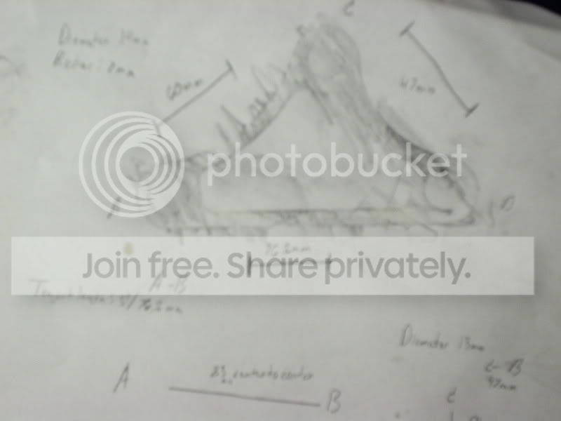
you don't need a compass, you can use your vernier as one. here is a more detailed instruction:
1. measure the diameter of the holes ie: 10mm
2. measure the shortest tangent distance between two holes ie: 50mm
3. add the diameter to the measurement taken in step 2 (10+50=60mm) and scribe a line exactly that length onto your piece of material to be used for the flange. RED LINE
4. repeat step two measuring the tangent distance between the blue and green hole. ie: 75mm
5. add the diameter (10+75=85mm) and scribe an arc from the blue hole end of the red line with a radius of 85mm.
6. repeat step 4 and 5 measuring the distance between the purple and green hole ie: 70mm... so 10+70=80mm, scribe another arc with a 80mm radius from the purple hole end of the red line.
7. center punch a point where the two arc radius intersect to locate the green hole on your flange material.
8. start drilling and cutting!
Thread Starter
Honda-Tech Member
Joined: Aug 2004
Posts: 4,638
Likes: 0
From: Altamonte Springs/Orlando, Florida, USA
<TABLE WIDTH="90%" CELLSPACING=0 CELLPADDING=0 ALIGN=CENTER><TR><TD>Quote, originally posted by G2turbo_terror »</TD></TR><TR><TD CLASS="quote">hmmm, this is more accurate than rubber cement/single layer cardboard and an exacto knife  </TD></TR></TABLE>
Yeah it is lol it's a lil blurry but I got some things into perspective.
<TABLE WIDTH="90%" CELLSPACING=0 CELLPADDING=0 ALIGN=CENTER><TR><TD>Quote »</TD></TR><TR><TD CLASS="quote">
Whats the method for 4+ holes? </TD></TR></TABLE>
I'd guess it would be the same? I think. I have to do the other side of the engine too which has 4 holes.

Modified by MidShipCivic at 5:36 PM 11/22/2007
</TD></TR></TABLE>Yeah it is lol it's a lil blurry but I got some things into perspective.
<TABLE WIDTH="90%" CELLSPACING=0 CELLPADDING=0 ALIGN=CENTER><TR><TD>Quote »</TD></TR><TR><TD CLASS="quote">
Whats the method for 4+ holes? </TD></TR></TABLE>
I'd guess it would be the same? I think. I have to do the other side of the engine too which has 4 holes.
Modified by MidShipCivic at 5:36 PM 11/22/2007
OG Fabricator
Joined: Feb 2005
Posts: 1,864
Likes: 1
From: Burlington, Ont., Canada
<TABLE WIDTH="90%" CELLSPACING=0 CELLPADDING=0 ALIGN=CENTER><TR><TD>Quote, originally posted by G2turbo_terror »</TD></TR><TR><TD CLASS="quote">
Whats the method for 4+ holes? </TD></TR></TABLE>
same deal applies, just use two holes to find the location of a third. you can double check the locations by going backwards, or using different holes, etc. this is how i draw up all my flanges from gaskets that are sent to me. it isn't that complicated once you figure out how it works. if you give me the dimensions, i can draw up a quick cad file for you or post a pic with some accurate dimensions.
aaron

Thread
Thread Starter
Forum
Replies
Last Post
justYncredible
Forced Induction
4
May 16, 2012 08:44 AM