

CNC Stainless Brake Cooling

Thread Starter
Honda-Tech Member
Joined: Nov 2006
Posts: 573
Likes: 0
From: Preston, Lancashire, United Kingdom
Hi there- im new in these parts- hardly posted 
i thought i would post up my newest custom addition
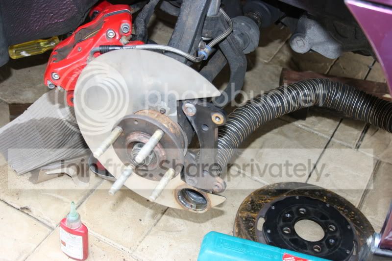
Front brakes are 12.5" Wilwood and the rear are 260mm.
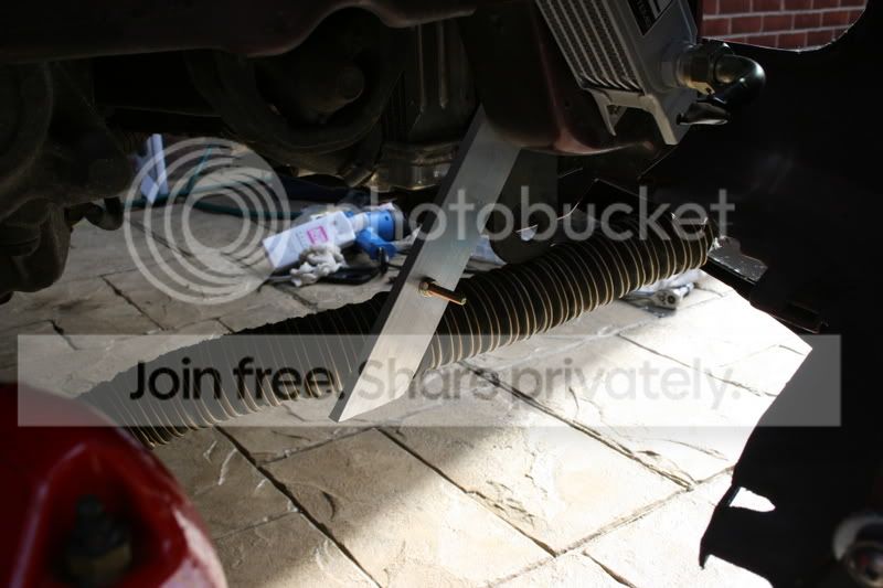
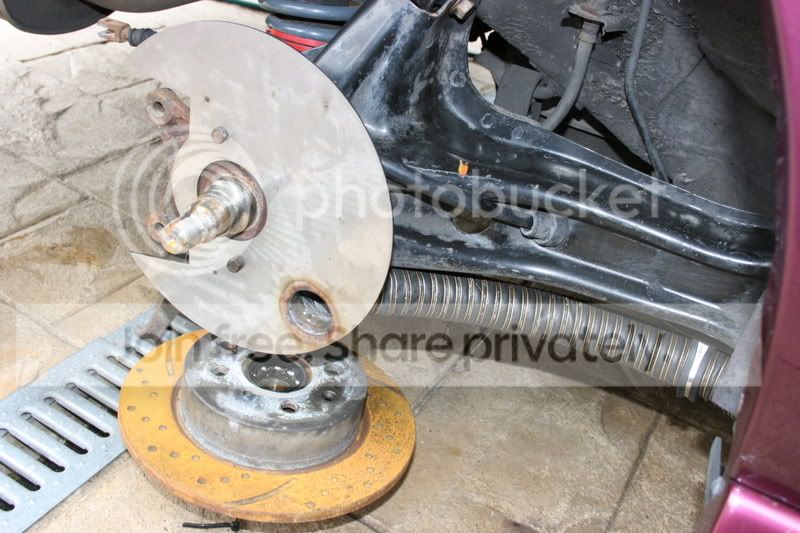
I have removed the ali dust guards from the back and laser cut some plates that completely cover the area behind, right up to the calipers. A stainless tube is welded at an angle to the back plate- and using some kevlar hose, receives air from the front splitter and rear side skirts-
im yet to fashion the intakes out of fibreglass (any ideas with that would be great as im struggling)
Heres the pictures- if anyone is interested;
i thought i would post up my newest custom addition
Front brakes are 12.5" Wilwood and the rear are 260mm.
I have removed the ali dust guards from the back and laser cut some plates that completely cover the area behind, right up to the calipers. A stainless tube is welded at an angle to the back plate- and using some kevlar hose, receives air from the front splitter and rear side skirts-
im yet to fashion the intakes out of fibreglass (any ideas with that would be great as im struggling)
Heres the pictures- if anyone is interested;

Thread Starter
Honda-Tech Member
Joined: Nov 2006
Posts: 573
Likes: 0
From: Preston, Lancashire, United Kingdom
Thats a good point, its fairly thick stainless, so i guess it would act as a heatsink - ill look into it.
I think the idea generally works- the system is pretty much standard on the dedicated track cars ive seen- i dont suppose it would be very good to autox, just adding to the unsprung weight...
I think the idea generally works- the system is pretty much standard on the dedicated track cars ive seen- i dont suppose it would be very good to autox, just adding to the unsprung weight...
Honda-Tech Member
Joined: Sep 2003
Posts: 3,234
Likes: 0
From: Austin, Republic of Texas
Any good performance shop will have plastic or FRP scoops for the front that have a molded-in outlet that fits the hose. They generally look like this:


Honda-Tech Member
Joined: Jun 2001
Posts: 590
Likes: 0
From: Tampa, FL, USA
When I was doing car prep for road racing we ran similar setups on our cars. If you go to pegasus racing they also sell some small inline fans that are cheap, small and push a decent cfm. I was going to test them on a car but we wrecked it at Sebring before I got to test the fans. Looks good.
Trending Topics
Thread Starter
Honda-Tech Member
Joined: Nov 2006
Posts: 573
Likes: 0
From: Preston, Lancashire, United Kingdom
Crikey- more replies than i expected!
Thats more than correct- these things should be aimed at the centre of the disc (on the front) so the centrifugal action of the vanes causes a vacuum in the centre- drawing in the fresh air. The back is a solid disc so it doesn't matter.
Unfortunately on the front, i couldnt get closer to the hub without interfering with the steering under full lock, plus the wilwood rotors have a very wide bell, so even though the inlets are quite close to the outside, the flow still catches the hub recess to an extent...
I have seen those fans before.. It would have been nice to see your results (and maybe the car not wrecked too
  ), im trying to keep the weight of all these "good ideas" down though so it isnt detrimental.
The hose is actually a kevlar composite - fire retardant, i "borrowed" it from work (i work for the aerospace industry) its very light for its size, and very flexible- you dont notice the 2" tubes on the front rotors from the wheel at all.
Thanks for all your replies!!!
Thats more than correct- these things should be aimed at the centre of the disc (on the front) so the centrifugal action of the vanes causes a vacuum in the centre- drawing in the fresh air. The back is a solid disc so it doesn't matter.
Unfortunately on the front, i couldnt get closer to the hub without interfering with the steering under full lock, plus the wilwood rotors have a very wide bell, so even though the inlets are quite close to the outside, the flow still catches the hub recess to an extent...
I have seen those fans before.. It would have been nice to see your results
(and maybe the car not wrecked too ), im trying to keep the weight of all these "good ideas" down though so it isnt detrimental.The hose is actually a kevlar composite - fire retardant, i "borrowed" it from work (i work for the aerospace industry) its very light for its size, and very flexible- you dont notice the 2" tubes on the front rotors from the wheel at all.
Thanks for all your replies!!!
Honda-Tech Member
Joined: Dec 2005
Posts: 314
Likes: 0
From: Yorba Linda, ca, United States of America
I can walk you through laying fiberglass, its pretty simple and the materials are really cheap. Can you post pics of where you want to create the opening?
Thread Starter
Honda-Tech Member
Joined: Nov 2006
Posts: 573
Likes: 0
From: Preston, Lancashire, United Kingdom
Here is the photo- hopefully you can see the annotations.
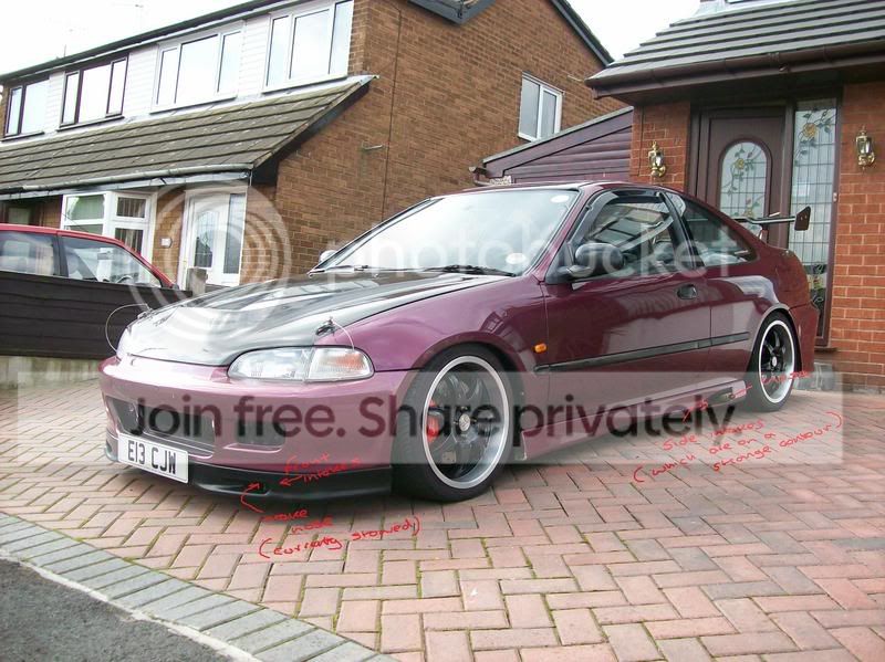
Its the shapes i am struggling with, im having a go with my father in law (used to have a boat so he knows grp) with one idea. But any help would be fantastic!!
Thanks alot
Its the shapes i am struggling with, im having a go with my father in law (used to have a boat so he knows grp) with one idea. But any help would be fantastic!!
Thanks alot

Honda-Tech Member
Joined: May 2003
Posts: 2,057
Likes: 1
From: mother russia
<TABLE WIDTH="90%" CELLSPACING=0 CELLPADDING=0 ALIGN=CENTER><TR><TD>Quote, originally posted by b16_DIM »</TD></TR><TR><TD CLASS="quote">I can walk you through laying fiberglass, its pretty simple and the materials are really cheap. Can you post pics of where you want to create the opening?</TD></TR></TABLE>
please break it down for us.
please break it down for us.
Honda-Tech Member
Joined: Apr 2005
Posts: 1,895
Likes: 0
From: Lincoln, Ne, USA
<TABLE WIDTH="90%" CELLSPACING=0 CELLPADDING=0 ALIGN=CENTER><TR><TD>Quote, originally posted by MidShipCivic »</TD></TR><TR><TD CLASS="quote">Isn't the fresh air supply for the vent suppose to go into the center off the rotor to be drawn in by the vanes.</TD></TR></TABLE>
The vanes create a low pressure zone behind the rotor....so I wouldn't worry about it.
The vanes create a low pressure zone behind the rotor....so I wouldn't worry about it.
Honda-Tech Member
Joined: Aug 2004
Posts: 4,638
Likes: 0
From: Altamonte Springs/Orlando, Florida, USA
<TABLE WIDTH="90%" CELLSPACING=0 CELLPADDING=0 ALIGN=CENTER><TR><TD>Quote, originally posted by k24em2 »</TD></TR><TR><TD CLASS="quote">
The vanes create a low pressure zone behind the rotor....so I wouldn't worry about it.</TD></TR></TABLE>
So thats where it is suppose to go!
The vanes create a low pressure zone behind the rotor....so I wouldn't worry about it.</TD></TR></TABLE>
So thats where it is suppose to go!
Thread Starter
Honda-Tech Member
Joined: Nov 2006
Posts: 573
Likes: 0
From: Preston, Lancashire, United Kingdom
<TABLE WIDTH="90%" CELLSPACING=0 CELLPADDING=0 ALIGN=CENTER><TR><TD>Quote, originally posted by MidShipCivic »</TD></TR><TR><TD CLASS="quote">
So thats where it is suppose to go! </TD></TR></TABLE>
Only the front rotors create the lower pressure, because they are wilwood discs, the hubs are quite large and when you look at the completed assembly- its obvious that the duct goes to the area behind the hub. So it still works as its intended to..
Honda-Tech Member
Joined: Dec 2005
Posts: 314
Likes: 0
From: Yorba Linda, ca, United States of America
Looks like you already have openings in the front lip and side skirts, this should make the task much easier.
Is your plan to create a fiberglass part to mount to the front lip (or skirt) that would taper down into a short cylinder that your kevlar tube can be mounted to using a clamp?
Do you want to make this piece a permanent addition to the lip/skirt or removable?
<TABLE WIDTH="90%" CELLSPACING=0 CELLPADDING=0 ALIGN=CENTER><TR><TD>Quote, originally posted by Mr.E.G. »</TD></TR><TR><TD CLASS="quote">
please break it down for us. </TD></TR></TABLE>
Ha, I have a feeling I'm about to get burned I'm not some pro pre-preg CF layer, I picked up the basics working on my Sculpture degree.
Is your plan to create a fiberglass part to mount to the front lip (or skirt) that would taper down into a short cylinder that your kevlar tube can be mounted to using a clamp?
Do you want to make this piece a permanent addition to the lip/skirt or removable?
<TABLE WIDTH="90%" CELLSPACING=0 CELLPADDING=0 ALIGN=CENTER><TR><TD>Quote, originally posted by Mr.E.G. »</TD></TR><TR><TD CLASS="quote">
please break it down for us. </TD></TR></TABLE>
Ha, I have a feeling I'm about to get burned
I'm not some pro pre-preg CF layer, I picked up the basics working on my Sculpture degree.
Honda-Tech Member
Joined: Aug 2004
Posts: 4,638
Likes: 0
From: Altamonte Springs/Orlando, Florida, USA
I don't see how the rear negative air pressure source is any different from the front rotor.
Edit : I see what you're trying to say it's in reference to your application because you aren't using vented in the rear.
Modified by MidShipCivic at 1:04 PM 10/5/2007
Edit : I see what you're trying to say it's in reference to your application because you aren't using vented in the rear.
Modified by MidShipCivic at 1:04 PM 10/5/2007
Thread Starter
Honda-Tech Member
Joined: Nov 2006
Posts: 573
Likes: 0
From: Preston, Lancashire, United Kingdom
<TABLE WIDTH="90%" CELLSPACING=0 CELLPADDING=0 ALIGN=CENTER><TR><TD>Quote, originally posted by b16_DIM »</TD></TR><TR><TD CLASS="quote">Looks like you already have openings in the front lip and side skirts, this should make the task much easier.
Do you want to make this piece a permanent addition to the lip/skirt or removable?
Ha, I have a feeling I'm about to get burned I'm not some pro pre-preg CF layer, I picked up the basics working on my Sculpture degree. </TD></TR></TABLE>
Lol- yeh i plan to use those previously "ridiculous" vents to do the job, my power steering cooler, oil cooler, radiator and the intercooler will take up the only other "holes".
I would like to make them permanent, and im in the aerospace industry, unfortunately i missed out on the carbon fibre layup on my apprenticeship but hey.. probably would have been nice...
Do you want to make this piece a permanent addition to the lip/skirt or removable?
Ha, I have a feeling I'm about to get burned
I'm not some pro pre-preg CF layer, I picked up the basics working on my Sculpture degree. </TD></TR></TABLE>Lol- yeh i plan to use those previously "ridiculous" vents to do the job, my power steering cooler, oil cooler, radiator and the intercooler will take up the only other "holes".
I would like to make them permanent, and
im in the aerospace industry, unfortunately i missed out on the carbon fibre layup on my apprenticeship but hey.. probably would have been nice...
Honda-Tech Member
Joined: Dec 2005
Posts: 314
Likes: 0
From: Yorba Linda, ca, United States of America
Okay, you will need:
Foam core
Bondo
Fiberglass weave (I prefer weave to mat)
Fiberglass resin & hardener (I would recommend something with a 15-30 minute Working time for a project this size)
Cheap set of paint brushes
Plastic cups
Piece of wood (paint stirrer is fine)
Latex gloves
Respirator
Mold release compound (vasaline will work)
Exacto knife or heated styrofoam cutter
Razor blade or good pair of scissors
Paper
Remove the front lip and find a clean stable place to work. You may want to clamp the lip to a workbench to keep it steady. Be sure to place cloth between the clamp and the lip.
Insert a piece of foam core through the front of the lip and at least two inches past (I'm assuming that two inches will be sufficient distance to clamp your brake cooler). You will need to trim the foam core in order to get a good tight fit. I recommend using either an exacto knife (which will dull quickly) or a heated Styrofoam blade (most modeling/hobby stores will have them).
Use a masking tape to hold the foam core steady. If you are planning on having the lip repainted then use duct tape it will hold better.
Since you are looking for an exact cylinder to clamp onto I would use a hole saw the appropriate diameter to shape the cylinder. Remove the center drill bit guide from the hole saw if you are able to. Drill slowly and try not to break off the cylinder you are cutting. You can then use the exacto knife to cut the styrofoam down to the cylinder and you should have a general idea of your positive now.
NOTE: If you are using the heated styrofoam cutter you should wear your respirator, the fumes are toxic.
Use bondo to smooth out the styrofoam. Sand it down until you get a nice smooth shape. The more time you take on this part the less cleanup you will have later.
Use the paper to make a pattern for the fiberglass weave on the positive. (make sure to overlap onto the lip so that it will become one permanant piece) The weave will be a bit more flexible than the paper.
Cut the fiberglass weave and test fit it.
Once you have it the right shape cut a second piece. (I think you will only want two layers of fiberglass since this isn't really structural).
Sand the lip where you plan on overlapping materials and then clean the surface.
Apply the mold release compound to the positive. Do not apply mold release compound to the overlap area of the lip.
Have all your tools/materials layed out and handy. Be sure to wear your respirator and latex gloves.
Mix up the resin in the plastic cups. Review the instructions with the resin for determining how much hardener to add to the resin.
Apply a layer of resin to the positive and the lip using the cheap brushes. When the resin gets tacky apply a layer of fiberglass and another layer of resin on top of that. I recommend mixing only enough resin for 1 layer at a time. As the resin cures it will get hot and may melt your cup. Doing one layer at a time will allow you to throw away the cup before it melts. Again, once the resin gets tacky lay the second layer of fiberglass and apply a third layer of resin.
Let the resin dry undisturbed for 24 hours.
You should now be able to remove the positive. If you did a good job making the bondo smooth you may not need to do any work to the fiberglass other than a light sanding, primer, & paint.
I recommend reading up on the net for fiberglassing techniques as you can learn some other tips and tricks. Also read the instructions for all materials, they will provide you details such as how much hardener to use, how long the working time of the resin is, how long the resin takes to dry, etc�
Thread Starter
Honda-Tech Member
Joined: Nov 2006
Posts: 573
Likes: 0
From: Preston, Lancashire, United Kingdom
Thanks alot for that- its a great help ill do a bit more reading as you suggest but thats a great base to work with...
Ill put some photos up when ive finished them- thanks for your help!! Bear with me though- may take some time
Ill put some photos up when ive finished them- thanks for your help!! Bear with me though- may take some time

Thread
Thread Starter
Forum
Replies
Last Post