

Anyone want something drawn in Solidworks for free?

Thread Starter
Honda-Tech Member
Joined: Jun 2006
Posts: 224
Likes: 0
I'm working up my Solidworks skills and if anyone wants something drawn, and or would like to give advice on operating solidworks to its most potential that would be great 
I can't guarantee i can make it perfectly, so these drawings that are sent back should be checked by a professional
I can't guarantee i can make it perfectly, so these drawings that are sent back should be checked by a professional
Honda-Tech Member
Joined: Jul 2004
Posts: 5,463
Likes: 2
From: I'm everywhere Focker
Someone should do a how-to on how to basically design a manifold for us noob's at solidworks. I haven't been able to dedicate much time to it, but I'll love to mess around with some designs if I had that basic process down.
Thread Starter
Honda-Tech Member
Joined: Jun 2006
Posts: 224
Likes: 0
Yeah, I can do single parts and then attempt to do an assembly. I'm trying to figure out how to model this pipe i made but it's making me scratch my head :-p
Honda-Tech Member
Joined: Jul 2004
Posts: 5,463
Likes: 2
From: I'm everywhere Focker
Yeah, I mean, I assume you get the flange in then design the pipes as 90's and straights, then make an assembly. Only deal is I heard of "flex"....someone mentioned, but no "flex" button in solidworks so.... 
Junior Member
Joined: Oct 2005
Posts: 419
Likes: 0
From: Cleveland, OH, USA
In PRO/E the easiest way to do manifolds is draw the centerline of the runner from the flange to the collector and then extrude a pipe along the centerline. Then you can mess around with cuts. The real pain the *** is drawing part of the runner centerline, then having to make a new data plane to sketch in to draw the next part of the centerline when the angles of the two parts your drawing are not coplanar. I'm told solid works is easier, but I'm a pro-e guy.
Thread Starter
Honda-Tech Member
Joined: Jun 2006
Posts: 224
Likes: 0
let's go with the basics, what's the easiest way to make a 90 Degree 2.5'' pipe with say a 1.5d radius, start off with a 2d or 3d sketch? draw a circle? then extrude it some how at a 90 degree angle? or am i way off 
Trending Topics
i HAS questions ?
Joined: Feb 2003
Posts: 7,850
Likes: 0
From: OH
<TABLE WIDTH="90%" CELLSPACING=0 CELLPADDING=0 ALIGN=CENTER><TR><TD>Quote, originally posted by corrupt0r »</TD></TR><TR><TD CLASS="quote">in autocad i would use the revolve command to do that...i imagine theres a similar command in pro/e and solidworks</TD></TR></TABLE>
 Exactly how to do it.
Draw the ID and OD and a line a certain distance from the center of the two circles for the bend radius. There should be a button in the Solidworks menu that has a toroid (donut) with an arrow inside it. Click that and it should as you for the feature you want to revolve and what line you want to revolve it around. After that it should ask you how many degrees you want to revolve it.
Exactly how to do it.Draw the ID and OD and a line a certain distance from the center of the two circles for the bend radius. There should be a button in the Solidworks menu that has a toroid (donut) with an arrow inside it. Click that and it should as you for the feature you want to revolve and what line you want to revolve it around. After that it should ask you how many degrees you want to revolve it.

Honda-Tech Member
Joined: Jul 2004
Posts: 5,463
Likes: 2
From: I'm everywhere Focker
<TABLE WIDTH="90%" CELLSPACING=0 CELLPADDING=0 ALIGN=CENTER><TR><TD>Quote, originally posted by TurboSI56 »</TD></TR><TR><TD CLASS="quote">I've got that tool to work right one time, all the other times it always says i need to select an axis of revolution, but i cant duplicate the same thing i did before. </TD></TR></TABLE>
That's exactly where i was at last night. I need to continue working with it though. I've done five full tutorials so far, but nothing really has gotten me to work with that tool yet.
I made two circles, matching the dimensions of sch10 pipe, but then I didn't know if I should define the 2.25" height, or if I should draw an arc from the center of the circles, or what the heck I should do. I then just tried the revolve tool and tried selecting the origin, but that clearly isn't a line.
Should I do a 3d sketch of some type of line on the axis simulating the centerline of the pipe? Should I arc it, or does the revolve tool change it to an arc? I'm pretty much lost after the circles....lol.
Member
Joined: Jan 2003
Posts: 2,933
Likes: 1
From: northern, ma, US
hell you gusy are making it harder than it should be...most pie sizes etc are downloadable from macmastercar....dl, import, and start assembling....
im also a pro/e guy myself....and cadd is my true home
im also a pro/e guy myself....and cadd is my true home
Honda-Tech Member
Joined: Jan 2003
Posts: 117
Likes: 0
From: CA
<TABLE WIDTH="90%" CELLSPACING=0 CELLPADDING=0 ALIGN=CENTER><TR><TD>Quote, originally posted by TurboSI56 »</TD></TR><TR><TD CLASS="quote">I've got that tool to work right one time, all the other times it always says i need to select an axis of revolution, but i cant duplicate the same thing i did before. </TD></TR></TABLE>
Add a centerline/construction line to the sketch and 90% of the time it will pick up on it automatically... Hang on, I'll try and pop off a screen shot...
Dan
Add a centerline/construction line to the sketch and 90% of the time it will pick up on it automatically... Hang on, I'll try and pop off a screen shot...
Dan
Honda-Tech Member
Joined: Jan 2003
Posts: 117
Likes: 0
From: CA
<TABLE WIDTH="90%" CELLSPACING=0 CELLPADDING=0 ALIGN=CENTER><TR><TD>Quote, originally posted by Sifu »</TD></TR><TR><TD CLASS="quote">How the hell do you make shape transitions in solidworks? Like say I wanted a pipe that was square at one end and circle at the other?</TD></TR></TABLE>
A loft feature. Create your sketches and hit the loft button, it looks like a square transitioning to a circle...

A loft feature. Create your sketches and hit the loft button, it looks like a square transitioning to a circle...
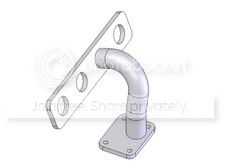
heres a header flange and tube I threw together. The tube is a single 3d sketch and a seperate sketch (the ID and OD of the tube) is drawn perpendicular to the centerline of the tube at either end and then "swept" along the 3d curve.
Thread Starter
Honda-Tech Member
Joined: Jun 2006
Posts: 224
Likes: 0
<TABLE WIDTH="90%" CELLSPACING=0 CELLPADDING=0 ALIGN=CENTER><TR><TD>Quote, originally posted by wreckedrex »</TD></TR><TR><TD CLASS="quote">
Sketch is green. You need a feature to revolve around...
Dan</TD></TR></TABLE>
Thanks, from all of the tutorials i read it just said sketch a line vertically and draw a circle next to it, none said anything about it being a centerline. Now it works perfectly. What would you use to model a pipe with multiple bends say a 3'' pipe that bends 4'' downstream at a 70 degree angle then 6'' after that at a 27 degree any direction.
<TABLE WIDTH="90%" CELLSPACING=0 CELLPADDING=0 ALIGN=CENTER><TR><TD>Quote, originally posted by TurboSI56 »</TD></TR><TR><TD CLASS="quote">
Thanks, from all of the tutorials i read it just said sketch a line vertically and draw a circle next to it, none said anything about it being a centerline. Now it works perfectly. What would you use to model a pipe with multiple bends say a 3'' pipe that bends 4'' downstream at a 70 degree angle then 6'' after that at a 27 degree any direction. </TD></TR></TABLE>
that would be a 3d sketch.
FWIW when I say centerline I mean the physical centerline of the tube, not the "centerline" command in Solidworks. You ARE right that it needs to be a regular sketched line, I just refer to it as the centerline of the tube as I'm sure others do too.
Honda-Tech Member
Joined: Dec 2000
Posts: 20,006
Likes: 3
From: Tampa, FL
<TABLE WIDTH="90%" CELLSPACING=0 CELLPADDING=0 ALIGN=CENTER><TR><TD>Quote, originally posted by Rosko »</TD></TR><TR><TD CLASS="quote">IIRC there was a tutorial in there of an oven rack looking thing. If you can find that tutorial it is EXACTLY what you are trying to accomplish. </TD></TR></TABLE>
There is. SolidWorks is pretty user friendly so it is a good program to start out on. I have been using Pro/E and SolidWorks since 2000. If you can get your work to spring for it, they teach an essentials and advanced course, as well as many others, that is pretty beneficial for a guy just starting out.
</TD></TR></TABLE>There is. SolidWorks is pretty user friendly so it is a good program to start out on. I have been using Pro/E and SolidWorks since 2000. If you can get your work to spring for it, they teach an essentials and advanced course, as well as many others, that is pretty beneficial for a guy just starting out.
Thread Starter
Honda-Tech Member
Joined: Jun 2006
Posts: 224
Likes: 0
yeah the oven rack tutorial always gives me a weird error towards the end that says error the path intersects its self? i've tried to get that tutorial right 20 times and i get the same error every time right after you draw the circle and try to do the command to make it round